Management Console UI
1. Introduction
The Management Console is a web-based user interface to interact with and configure an IoT system.
This document provides a reference to the different screens in the Console Web UI.
1.1 Prerequisites
To log into the Management Console a user account is required. Visit the Quick Overview guide for information about requesting an account.
1.2. Login URL
The URL for the Management Console will vary depending on the installation of the particular customer platform.
1.3. Demo URL
A demo version of the Management Console is available at https://demo.riotsecure.io.
2. User Interface Overview
2.1. Navigation
The Management Console has a number of screens that are used to visualize or configure different aspects of the RIoT Secure Platform.
In the lower-left corner of the display is the main navigation menu. It consists of icons used to navigate between screens. This menu can be moved anywhere within the browser window by dragging it with the mouse.
| Icon | Meaning | Purpose |
|---|---|---|
| Dashboard | Display security and status information for deployed devices | |
| Map | Display a map showing all enrolled devices that have a location | |
| Devices | Display a list of all enrolled devices, perform firmware updates | |
| Users | Display a list of users and the currently active user account | |
| Packets | Display and manage the definition of data packets for communication | |
| Application Firmwares | Display and manage customer application firmwares | |
| Hardware Interfaces | Display and manage hardware interfaces | |
| Settings | Display tenant account information |
2.2. User Interface Button Icons
The Management Console uses the following icons for user interface command buttons.
| Icon | Meaning | Purpose |
|---|---|---|
| Create | Create a new object | |
| Edit | Open a form to view and edit an object | |
| View | Open a form to view an object | |
| Duplicate | Duplicate an object | |
| Delete | Delete an object | |
| Download | Download data for an object | |
| Installer download | Download RIoTInstaller for a device | |
| View Location | View the location of a device on the map |
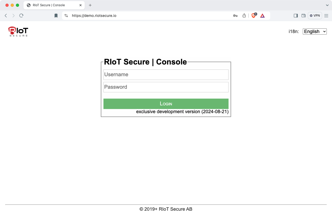
3. Login Screen
To login, fill in username (email address) and password.
4. Dashboard Screen
The Dashboard Screen displays an overview of the IoT deployment. This screen provides important security updates and status information for deployed devices (devices that are not yet enrolled are not included).
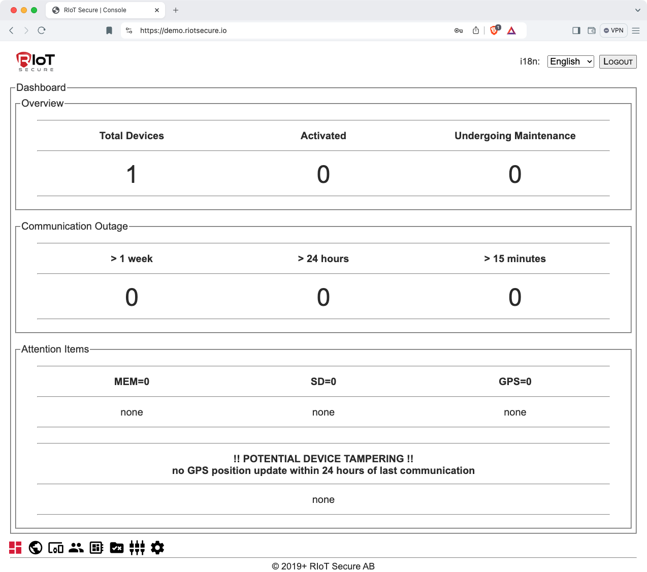
4.1. Dashboard Sections
| Section | Purpose |
|---|---|
| Overview | Number of deployed devices and their status |
| Communication Outage | Communication status summary |
| Attention Items | Device memory status, GPS status, and warning messages |
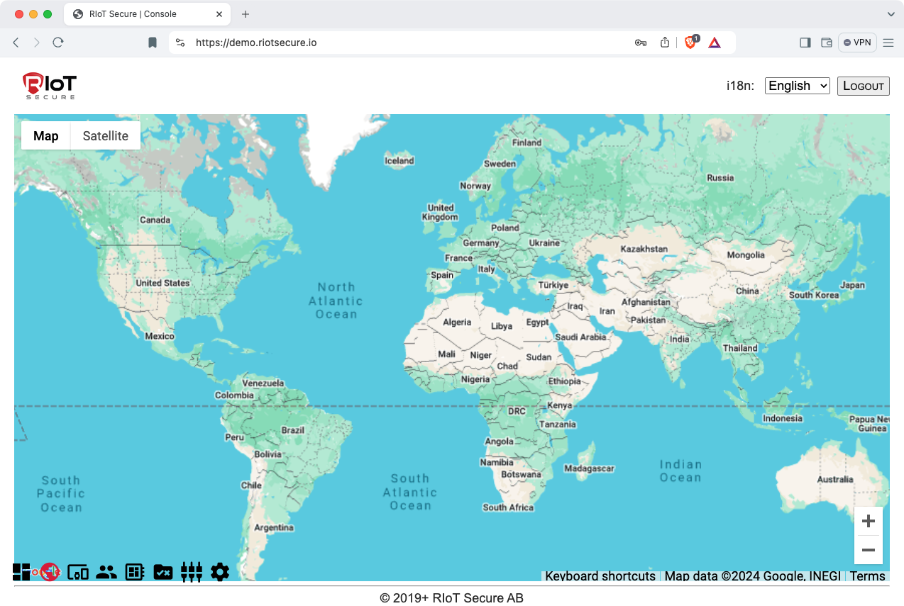
5. Map Screen
The Map Screen shows enrolled devices that has a location defined.
By clicking on a device icon, further information about the selected device is shown.
6. Devices Screen
The Devices Screen lists all the devices and handles their management within a deployment.
To view or make chances to a device (e.g. update the firmware); click on the pencil icon to open the device form.
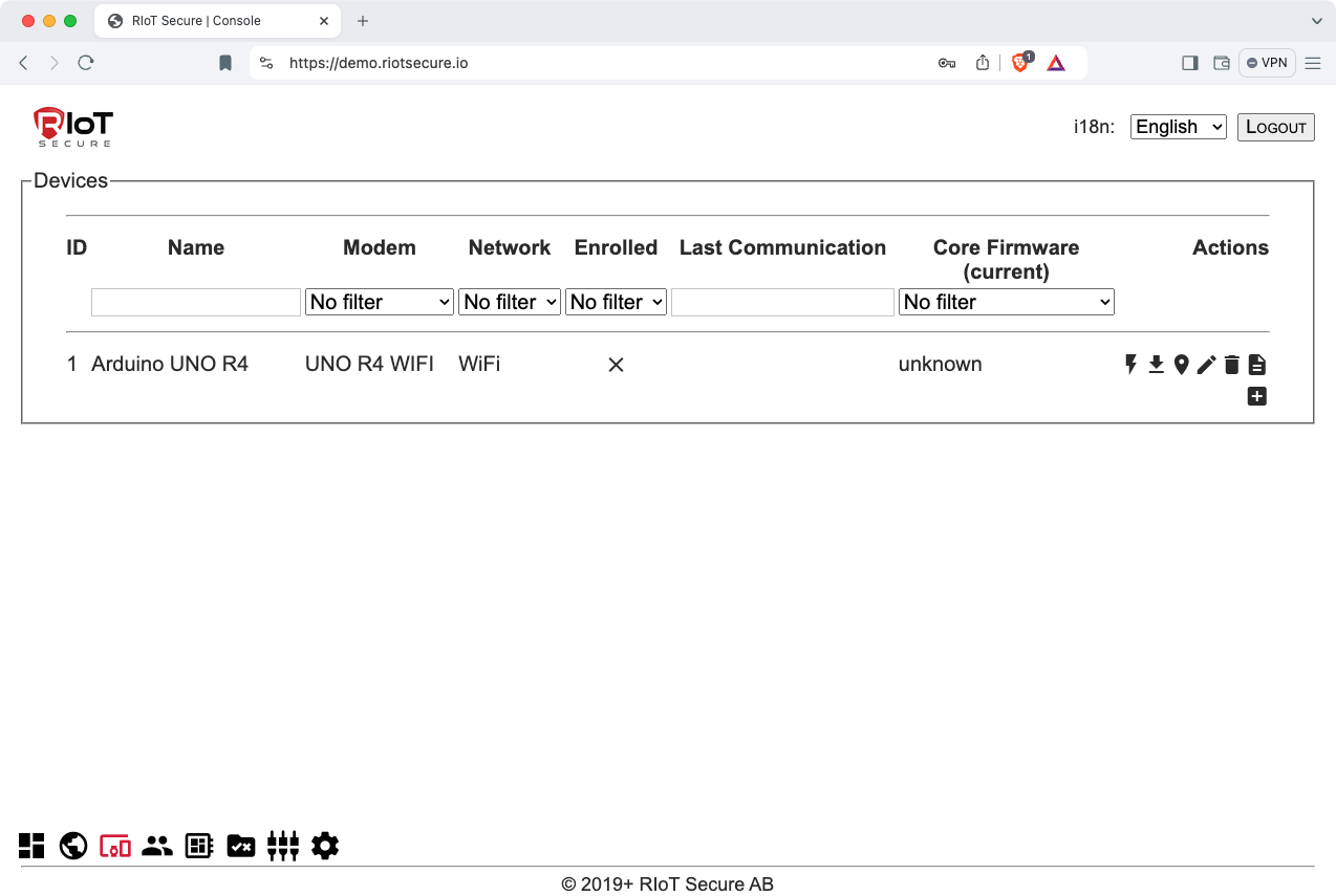
6.1. Device Fields
| Field | Purpose |
|---|---|
| Name | The device name |
| Modem | The microcontroller/board used for communication |
| Identifier | An internal identifier defined in the platform |
| Network | An internal identifier defined in the platform |
| Core Firmware | The FUSION Core Firmware |
| Hardware Interface | The FUSION interface (hardware design) used |
| Integration Enabled | Set if data should be relayed to the Integration URL |
6.2. Power Monitoring Fields
| Field | Purpose |
|---|---|
| Ignition Status | The current state of the ignition digital input PIN |
| Power Timestamp | When the last power information was provided |
| Power Properties | The various power properties (voltage, amp et al) |
6.3. Modem Information Fields
The modem information is based on the type of micrcontroller selected.
| Field | Purpose |
|---|---|
| IMEI | The IMEI of the communication module |
| ICCID | The ID of the SIM (subscriber identity) |
| Field | Purpose |
|---|---|
| MAC | The physical address of the network module |
| BSSID | The physical address of the network gateway module |
6.4. Network Settings Fields
The network settings are based on the selected modem microcontroller.
Depending on the network topology, different settings may be required – for example; WiFi devices will require an SSID at a bare minimum and a username/password to connect to the network. When using 3G or NB-IoT network; an APN (access point name) and a username/password to connect to the network.
| Field | Purpose |
|---|---|
| Net: SSID | The SSID for the WiFi network |
| Net: username | The username for the WiFi network (max 32 chars) |
| Net: password | The password for the WiFi network (max 32 chars) |
| Field | Purpose |
|---|---|
| Net: APN | The APN for the 3G / NB-IoT network |
| Net: username | The username for the network (max 32 chars) |
| Net: password | The password for the network (max 32 chars) |
6.5. GPS Location Fields
| Field | Purpose |
|---|---|
| GPS: latitude | The fixed latitude of the device (optional) |
| GPS: longitude | The fixed longitude of the device (optional) |
6.6. Microcontrollers Fields
| Field | Purpose |
|---|---|
| Name | The official microcontroller name |
| Identifier | An internal identifier defined in the microcontroller |
| Application Firmware | A firmware for the microcontroller |
7. Users Screen
The Users Screen lists all users of the tenant.
By clicking on a user, data can be edited.
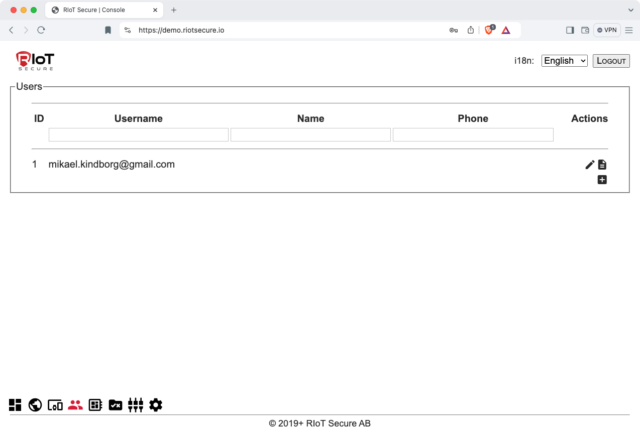
7.1. User Fields
| Field | Purpose |
|---|---|
| Username | The username of the user |
| Password | The password for the user (update only) |
| Password * | The password verification for the user |
| Name | The real-life name of the user |
| Phone | The phone number of the user |
7.2. Permissions
A key design of the platform is the granularity of user permissions in the management console.
When creating a user, templates are used to simplify the definition of permissions - they can be modified at any time. A user can only perform create, view, modify or delete tasks if they have permissions granted; this is enforced not only in the management console but also the REST API.
8. Packets Screen
The Packets Screen shows all the data packet definitions defined within a deployment.
Data packets are a critical component of the IoT deployment - as they deal with the definition and bit level representation of how data is communicated from the embedded client in a compact form and eventually unpacked into JSON format, relayed to the customer API for processing.
Data Packets are extremely compact in nature and include identification, length, padding and checksum attributes to ensure that no data can be incomplete or modified in any way during the transmission.
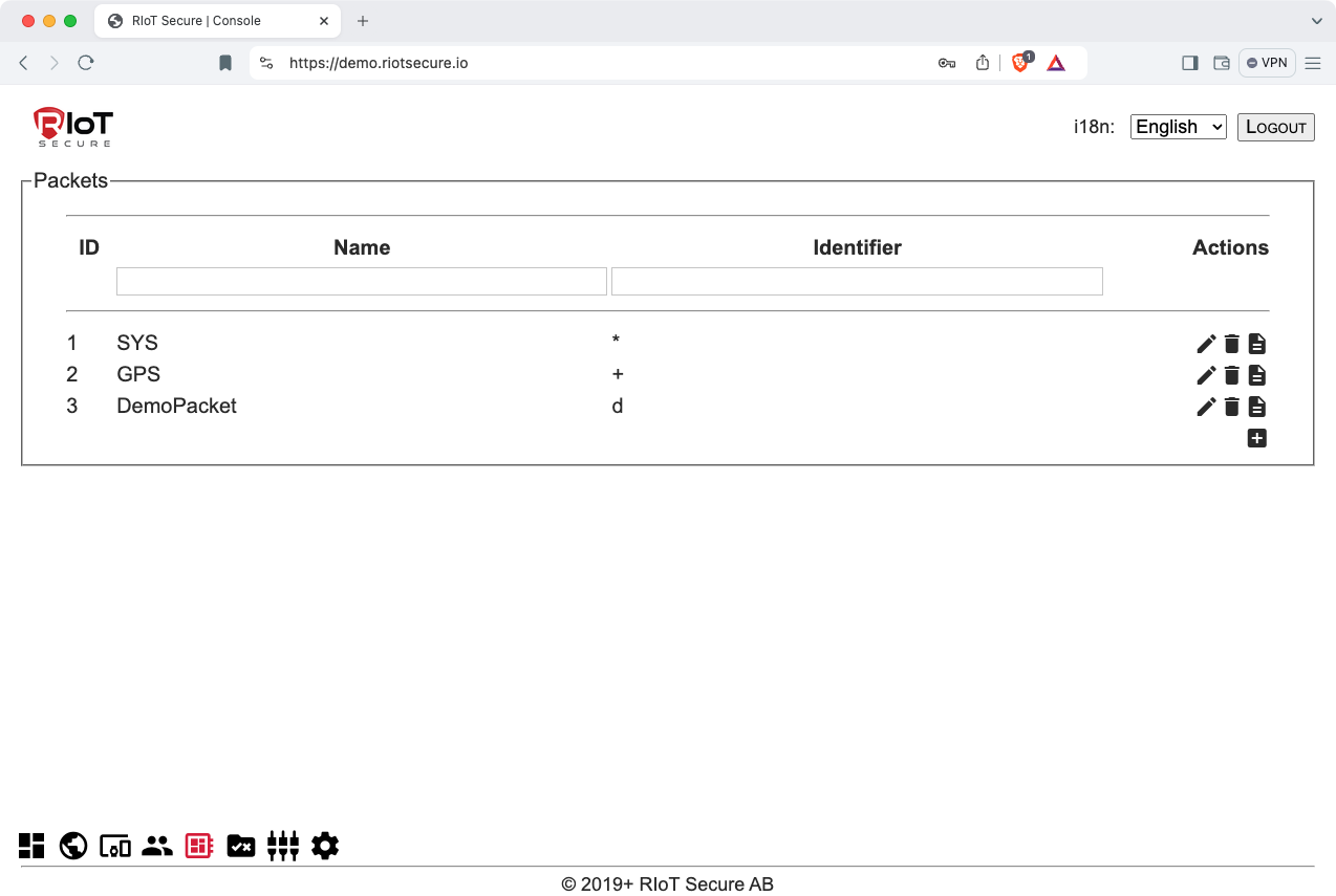
Related Documentation
Packet Editor9. Application Firmwares Screen
The Application Firmwares Screen lists all the application firmwares of the tenant.
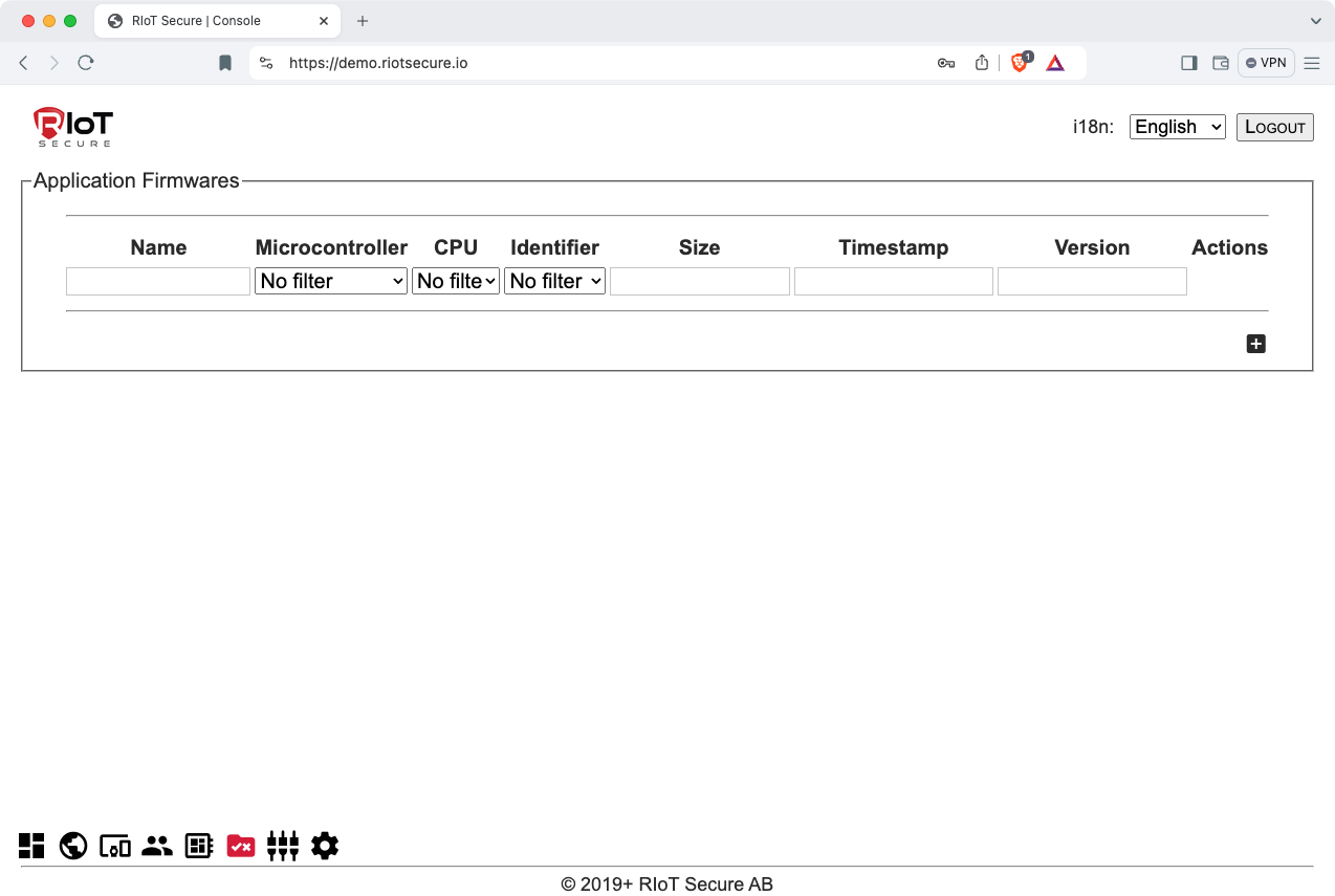
Related Documentation
Firmware Management9.1. Application Firmware Fields
| Field | Purpose |
|---|---|
| Name | The firmware name |
| Microcontroller | The target microcontroller of the firmware |
| Version | The unique version number |
| Identifier | An internal identifier defined in the platform |
| Description | A user readable description of the firmware |
| Upload File | Select the firmware file to upload to the platform |
9.2. Firmware Version Number Format
The application firmware version number is used to uniquely identify the firmware and to keep track of different firmware versions. The version number must be unique for each entry; however, if an entry is deleted, the old firmware version can be reused.
The version number consists of four digits between 0 and 255.
Note that the following version numbers are reserved by the system:
0.0.0.0
255.255.255.255
For the purpose of simplicity and easier management of firmware files - it is suggested to use a consistent naming convention; such as using the two first numbers as a project related identifier, and the last two for the major and minor firmware version, as in this pattern:
id1.id2.major.minor
For example, the following firmware version number:
1.1.0.1
has these fields:
| Field | Number |
|---|---|
| Device-id | 1 |
| Application-id | 1 |
| Major version | 0 |
| Minor version | 1 |
10. Hardware Interfaces Screen
The Hardware Interfaces Screen shows the different configurations available in a specific product deployment for interfacing between the modem and the application board of a FUSION Device. New hardware interfaces can be created for custom configurations.
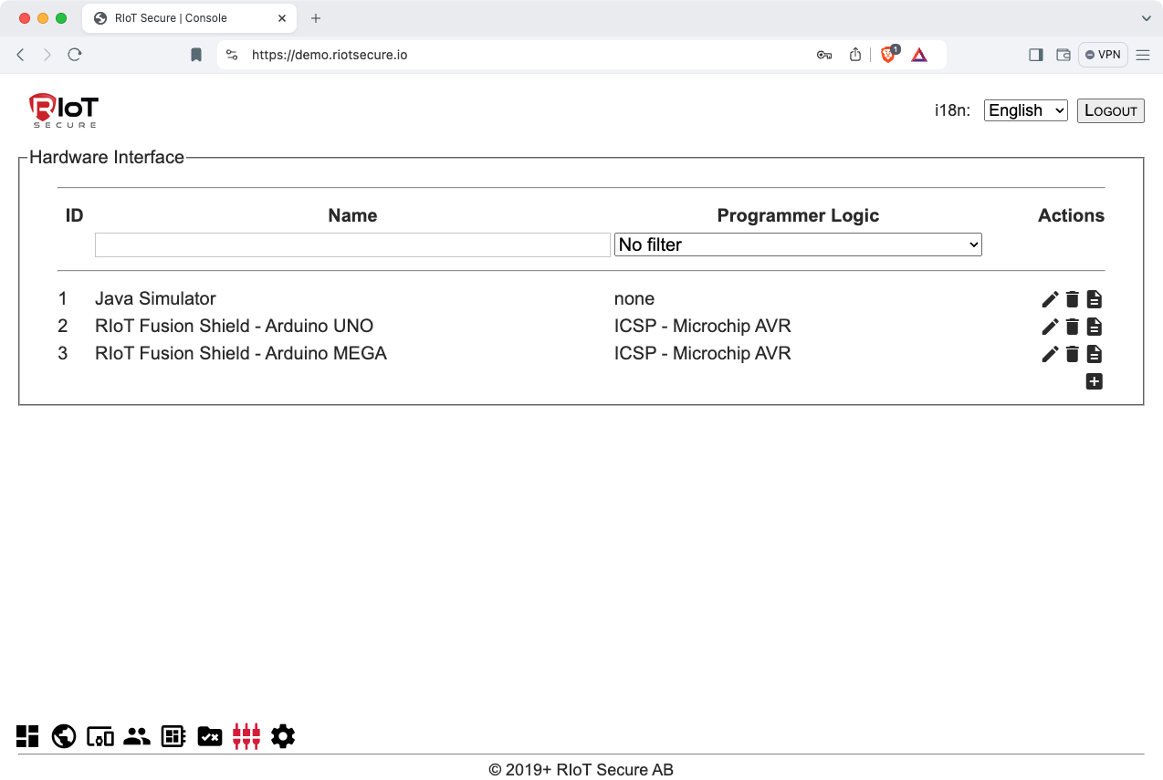
10.1. Hardware Interface Properties
| Field | Purpose |
|---|---|
| Name | The name of the hardware interface |
| Programmer Logic | The programmer logic used (in system programming) |
10.2. Hardware Pins
10.2.1. System
| Field | Purpose |
|---|---|
| LED: RTOS Heart Beat | The LED PIN showing the RTOS heart beat |
| LED: GPS Fix Acquired | The LED PIN showing a GPS fix has been acquired |
| LED: Internet Access | The LED PIN showing that there is internet |
| LED: Network Access | The LED PIN showing that there is carrier/network |
| SPI SS: microSD | The PIN used to select the microSD on the SPI bus |
| SPI SS: Flash Memory | The PIN used to select the flash memort on the SPI bus |
| Ignition Detect | The Digital Input PIN for detecting ignition status |
10.2.2. Power
| Field | Purpose |
|---|---|
| Main Power: Voltage | The analogue PIN detecting main power voltage |
| Main Power: Ampere | The analogue PIN detecting main power ampere |
| Power Cycle | The PIN used to trigger power-cycle via hardware |
10.2.3. In System Programming
| Field | Purpose |
|---|---|
| ISP Reset | The digital state for resetting the microcontroller |
| ISP Slave Detect | The PIN used to detect the presence of a microcontroller |
| ISP Output Enable | The PIN used to enable ISP interface pins |
| ISP Selector 0 | Combined to select up to two microcontrollers |
| ISP Selector 1 | Combined to select up to four microcontrollers |
10.3 Microcontrollers
The Microcontrollers section shows the microcontroller(s) defined for the hardware interface.
11. Settings Screen
The Tenant Settings Screen contains information about the current tenant.
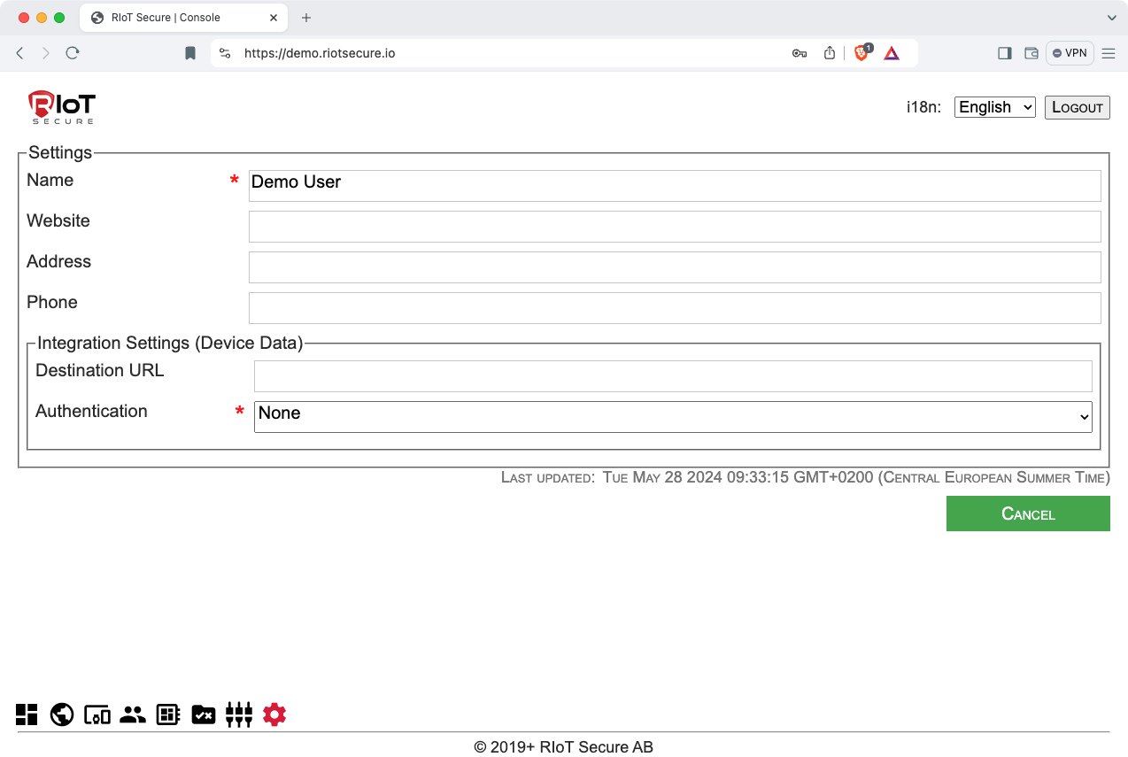
11.1. Settings Fields
| Field | Purpose |
|---|---|
| Name | The name of the tenant |
| Website | The web address of the tenant |
| Address | The physical address of the tenant |
| Phone | The phone number of the tenant |
| Destination URL | The customer cloud server URL to relay data packets to |
| Authentication | Authentication method used by the customer cloud server |