Packet Editor
1. Introduction
The Packet Editor in the Management Console is used to define data packets in device to customer cloud communication. Packets offer a compact binary representation of data.
The Device Communication documentation details how data packets are used and how to application firmware code that communicates with the customer cloud.
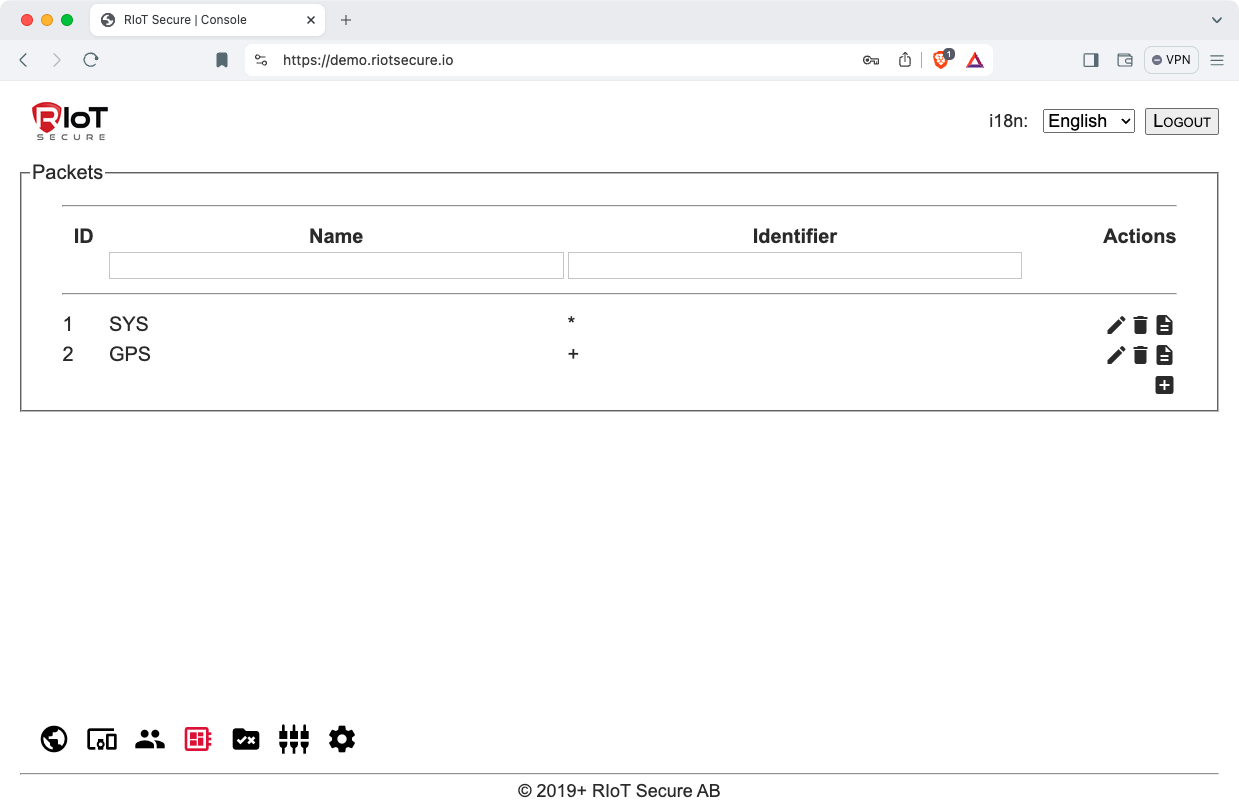
Packets are managed on the Packets Screen in the Management Console. This screen displays a list of defined packets in a table view. To the right of each row are icons that perform operations on packets.
Releated Documentation
Packet Reference Device Communication Reference Device Communication Tutorial REST API Overview2. Packet Component Structure
A packet consists of top-level fiels such as the packet name and identifier, and components that define the format of application specific data fields.
Components are used defined. Each packet can have one or more components. A component represents a value, for example temperature, ignition status, voltage, or some other sensor value used by the application.
There are several component formats. See the Device Communication Reference documentation for a specification of component types.
Using the packet editor, components can be added, edited, and deleted.
3. Packet Creation
To define a packet, a new packet is created, and one or more components are added.
3.1. Add a Packet Entry
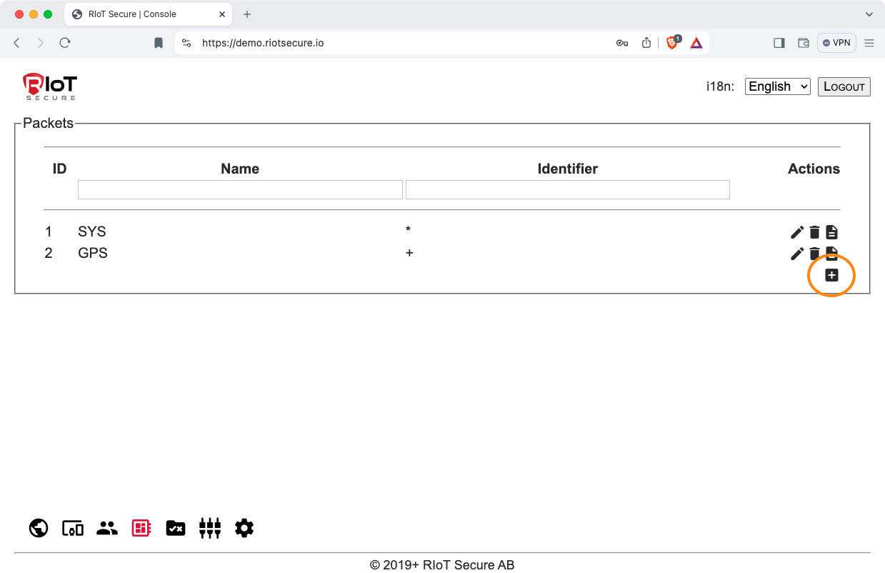
To add a new packet entry, click on the “+” icon on the Packets Screen. This opens a form for specification of packet details.
3.2. Packet Fields
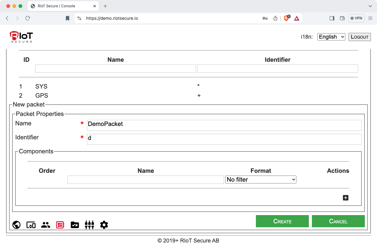
The top-level packet form has the following fields:
| Field | Purpose |
|---|---|
| Name | The packet name. |
| Identifier | A unique identifier for the packet. A packet identifier consists of a single byte character. |
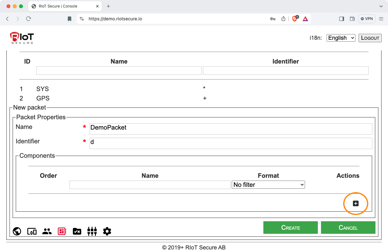
Fill in packet name and identifier:
3.3. Create Components
3.3.1. Add a New Component
A packet must have at least one component. To add a new component, click the “+” icon in the Components section of the form:
3.3.2. Specify the Component Name and Format
Define the component by filling the name and selecting the format.
| Field | Purpose |
|---|---|
| Name | The component name. |
| Format | The component format. Select the desired format from the field popup menu. |
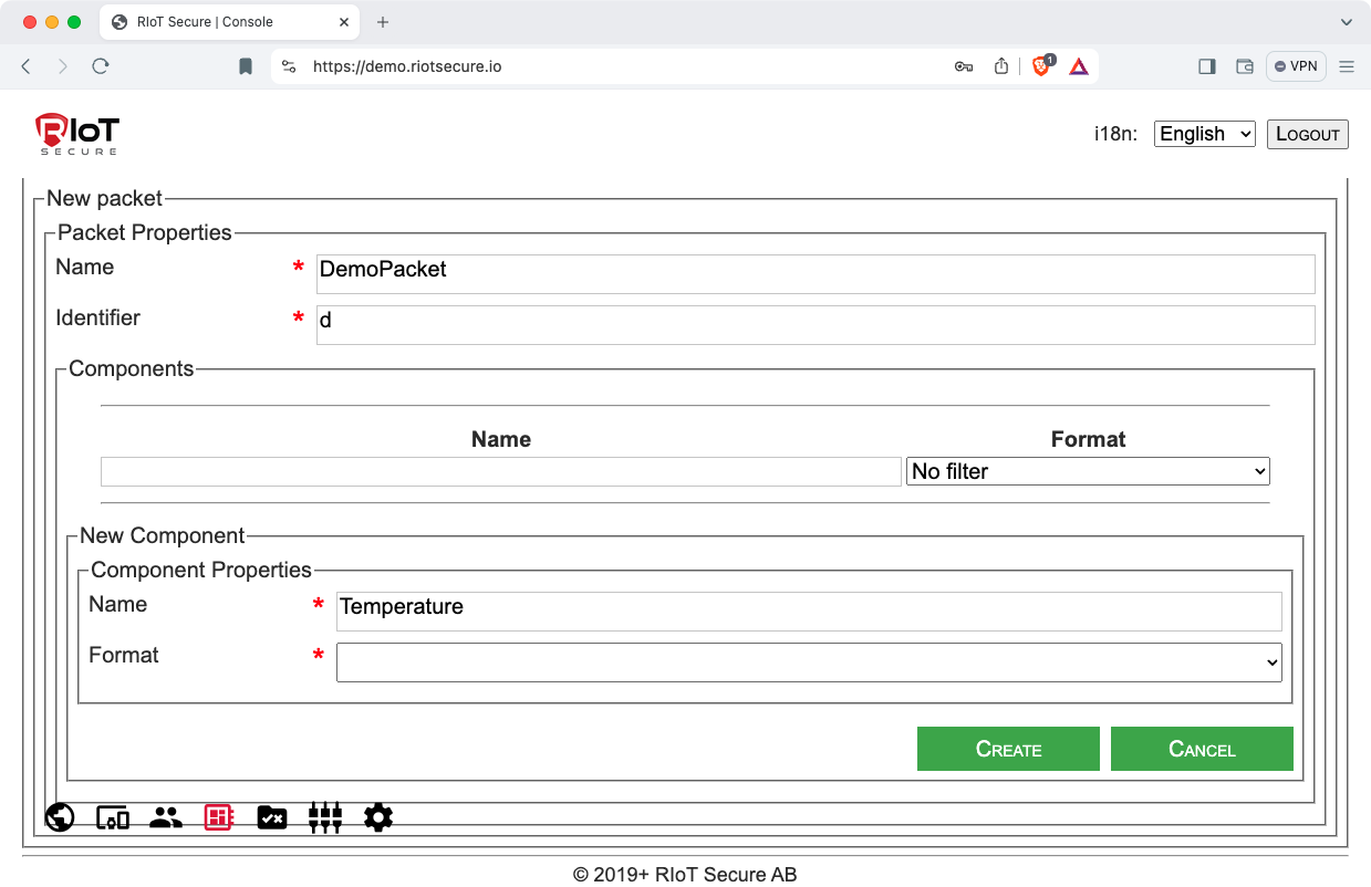
Fill in the component name:
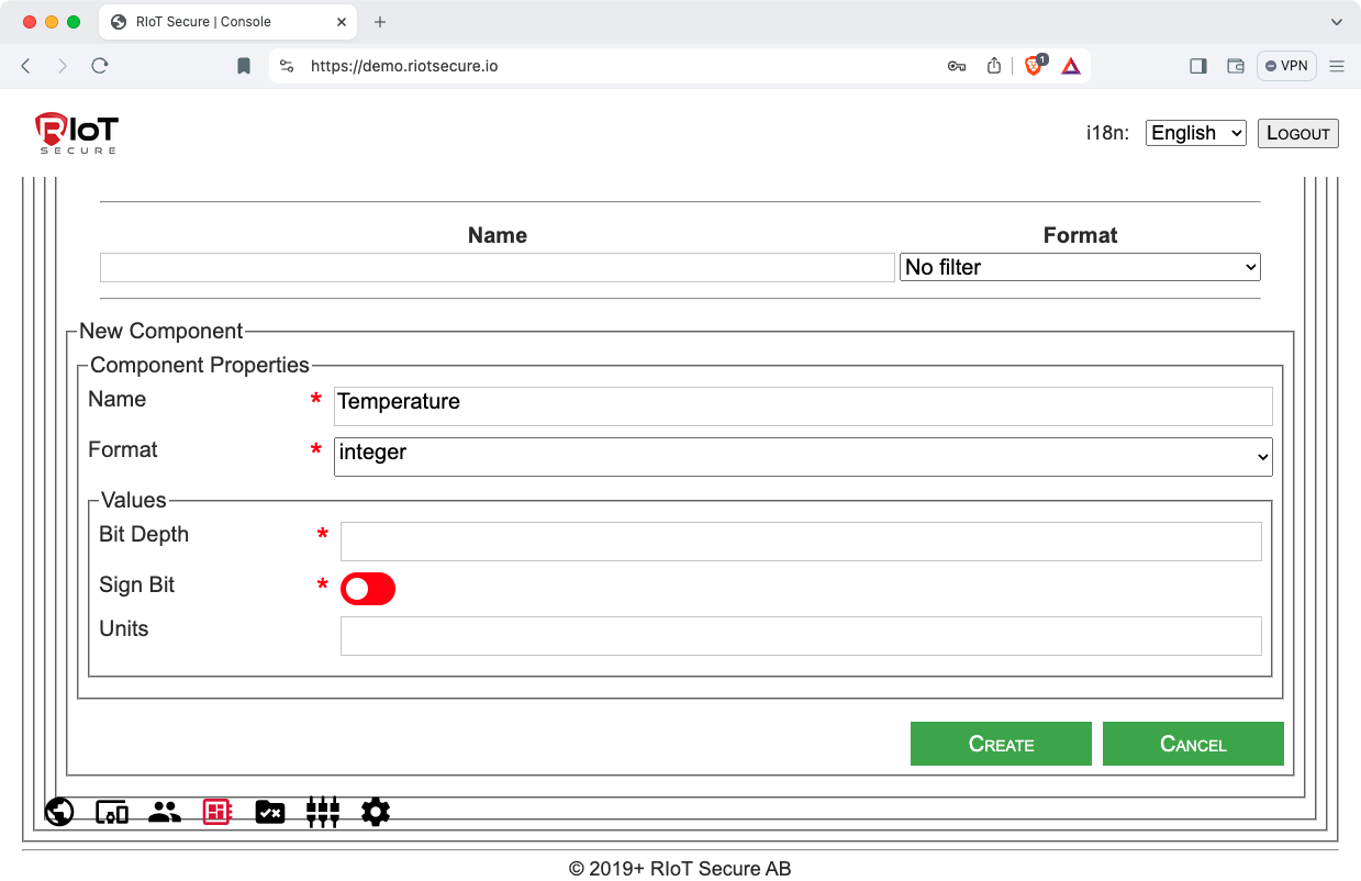
Select the component format. Depending on the format selected, different subforms will be displayed. In this example, the integer format has been selected:
3.3.3. Define the Component Bit Format
Each format type has their own fields, specifying the component data format at the bit level. The integer format type has the following fields:
| Field | Purpose |
|---|---|
| Bit Depth | The number of bits used to represent the data. |
| Sign Bit | Boolean selection that defines if signed or unsigned integer bit representation is used. |
| Units | Text field representing the unit measurment of the value. This field does not affect the bit-level representation of the value; it is intended to be used for readability. The Units field can be left blank. |
Here is an example where an 8-bit unsigned integer is used to represent the temperature value. The Units field is left blank in this example.

Consult the Packet Reference documentation for information about component format types. The REST API Overview reference also has a section about packet component formats.
3.3.4. Create the Component
Click the “Create” button to create the component.

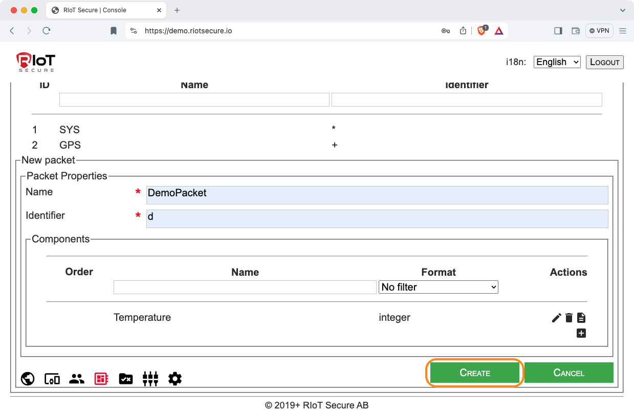
3.4. Save the Packet
To create and save the packet, click the “Create” button of the packet form:
4. Packet Management
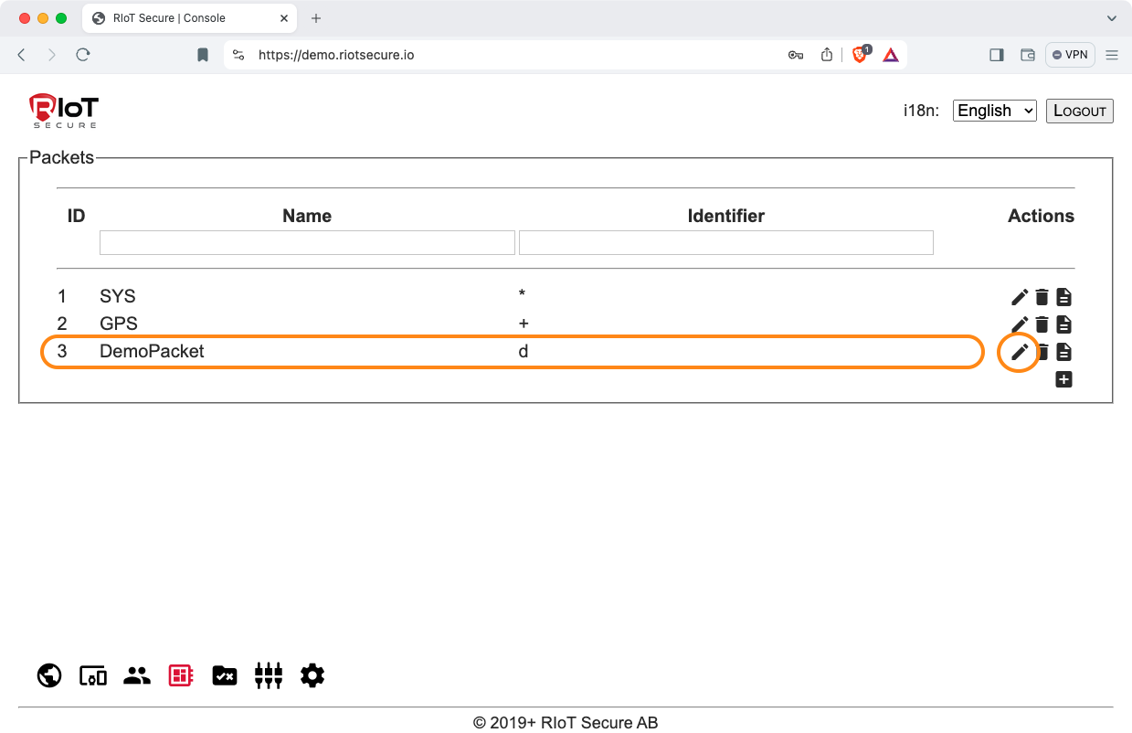
4.1. Edit or View a Packet
To edit or display a packet definition, click on a row in the table, or on the “pencil” icon. This will open the packet form.
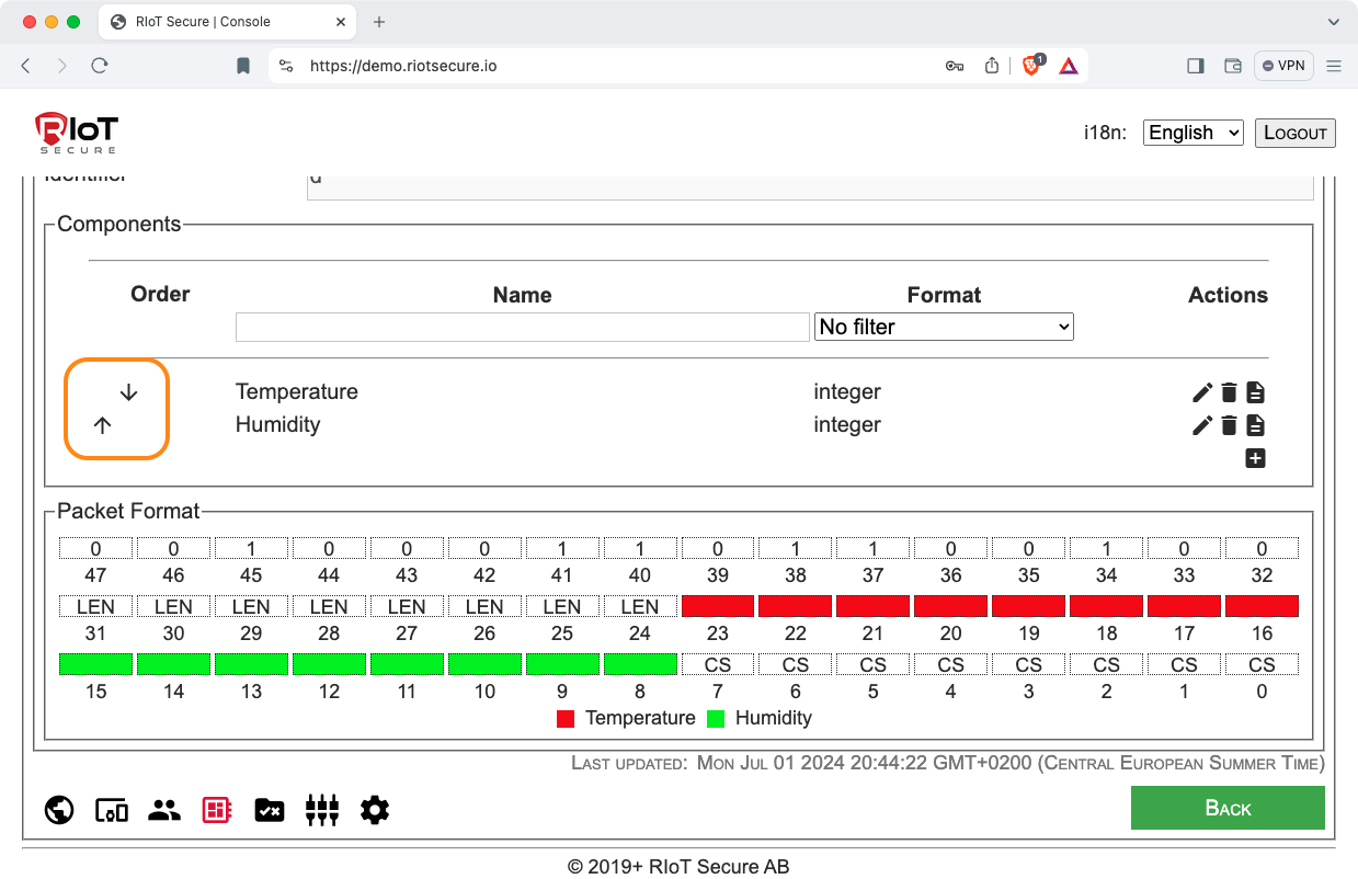
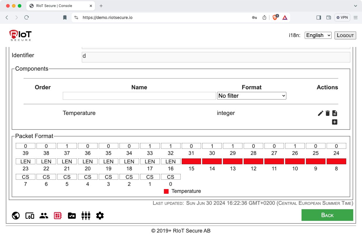
4.2. View Packet Bit Layout
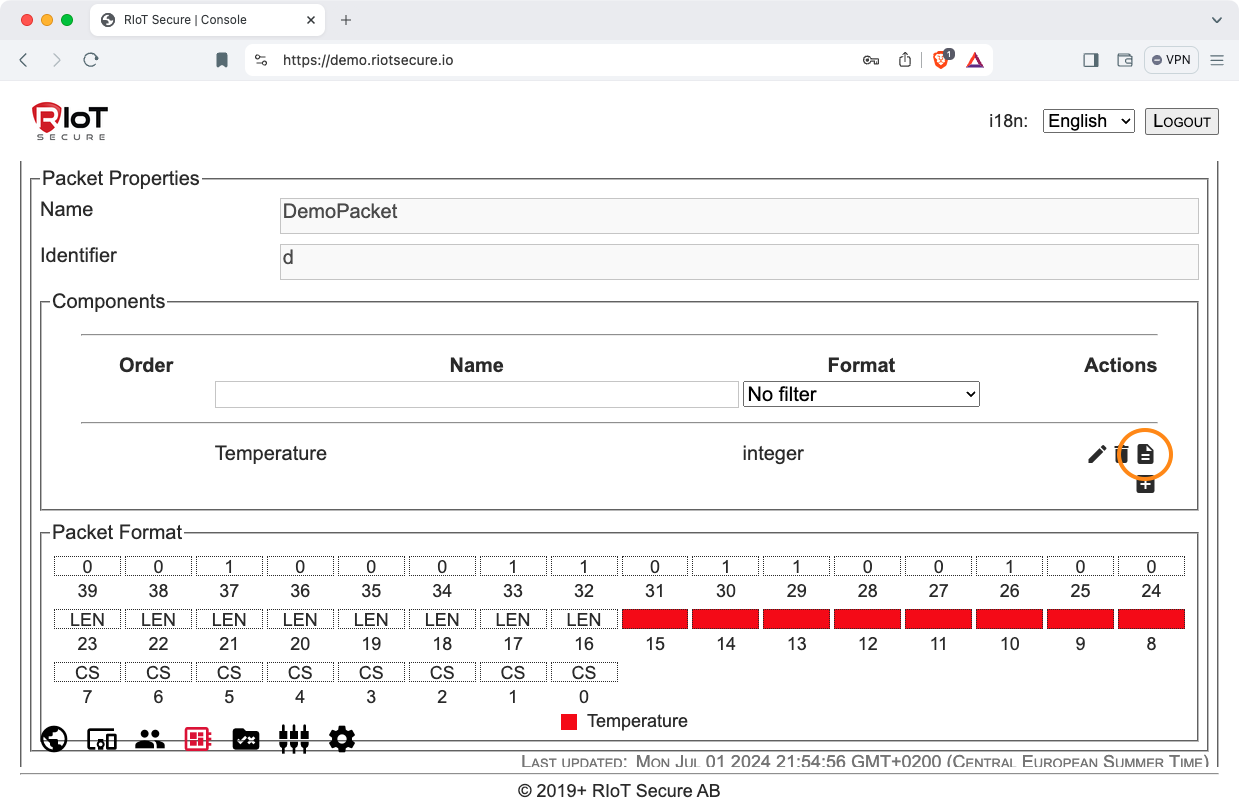
Scroll to the end of the packet form to view the packet bit-layout diagram. The diagram displays the layout in memory of the packet fields (packet header, packet length, and checksum), and the layout of the components.
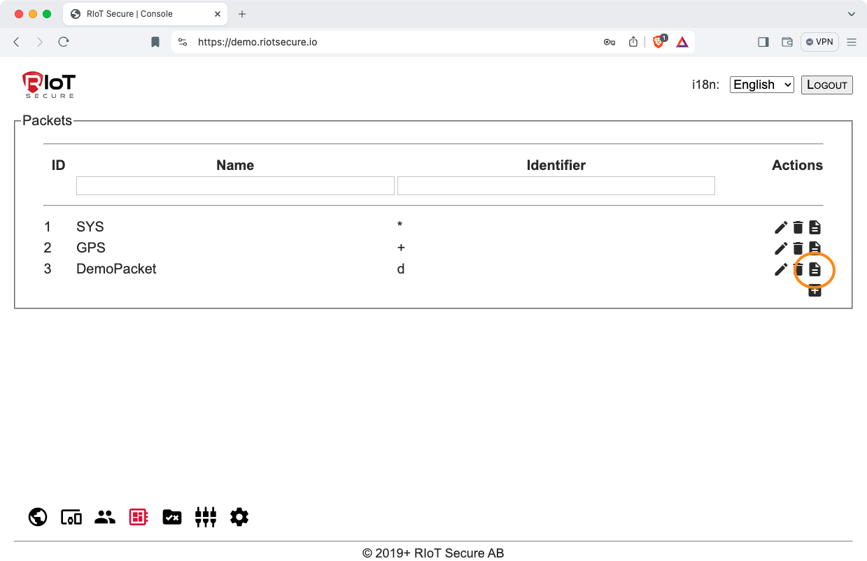
4.3. Copy a Packet
To create a new packet by copying an existing packet, click the “document” icon.
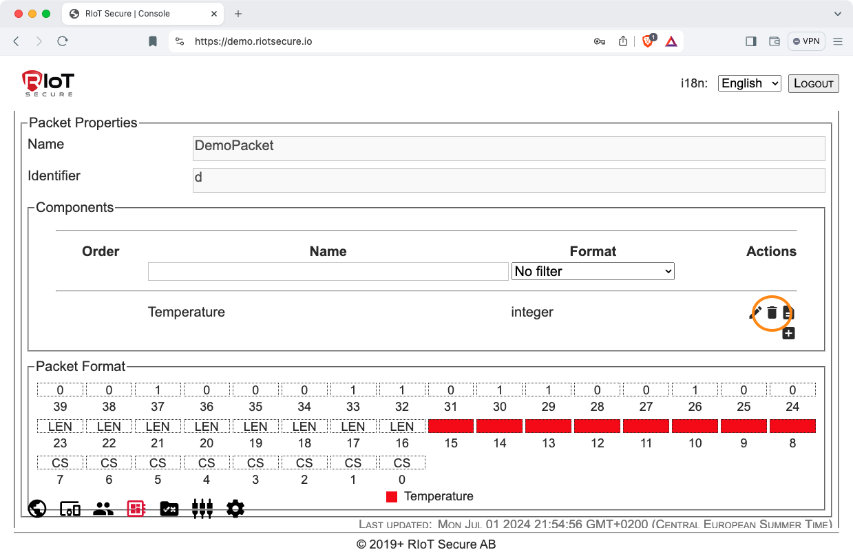
4.3. Delete a Packet
To delete a packet, click the “bin” icon.

5. Component Management
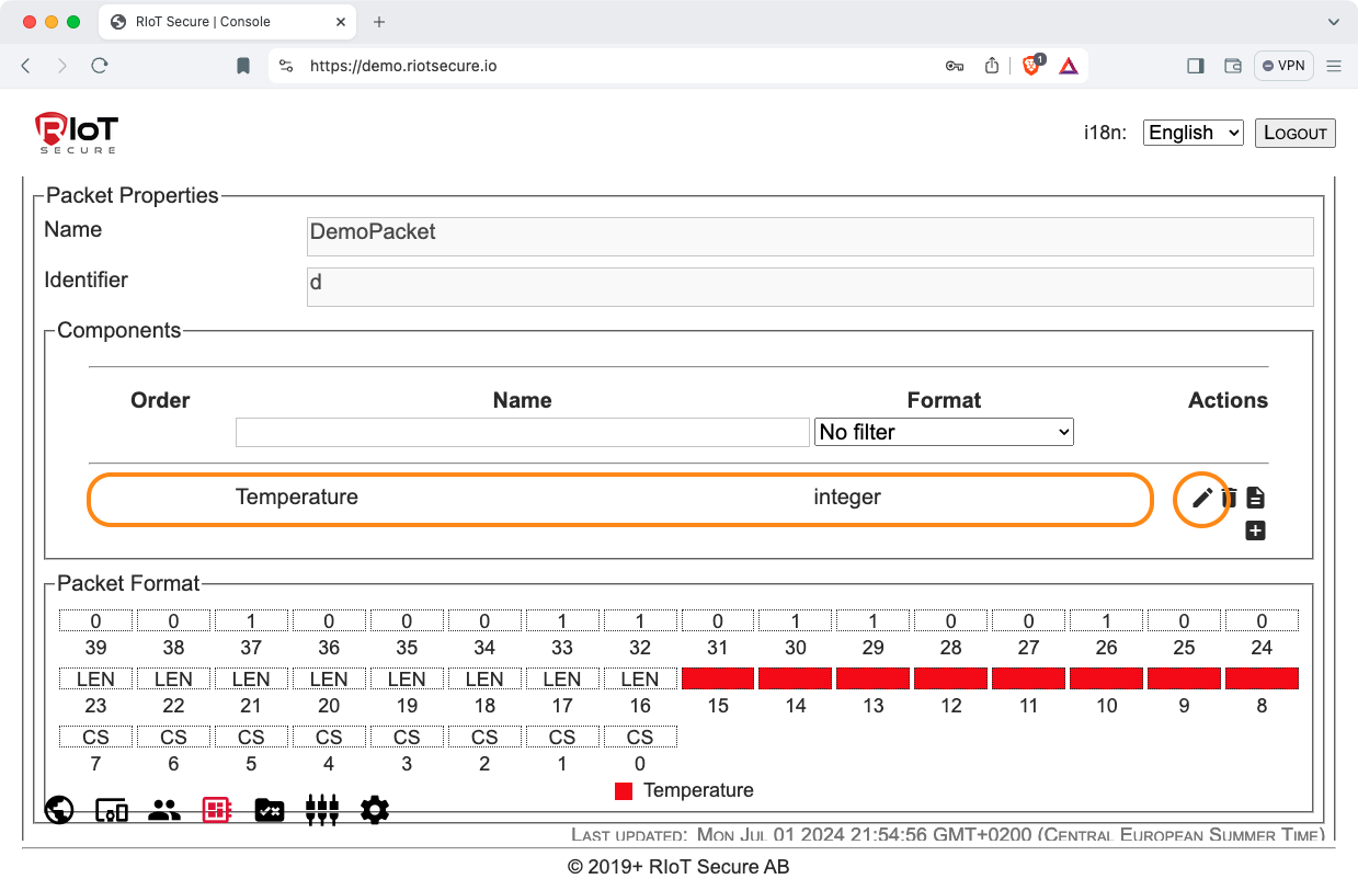
5.1. Edit or View a Component
To edit or display a component definition, click on a row in the component table, or on the “pencil” icon.
5.2. Copy a Component
To create a new component by copying an existing component, click the “document” icon.
5.3. Delete a Component
To delete a component, click the “bin” icon.
5.4. Change Component Order
If a packet has multiple components, the order can be changed using the arrow icons. The order affects the memory layout of the components.