Arduino IDE
The Arduino IDE (Integrated Development Environment) is used to write firmware for embedded devices. It is a tool that is widely used, and it has become an industry standard for embedded development. It runs on a computer that is connected to an embedded device (board) over the serial port (using a USB cable).
The Arduino IDE is used to create customer application firmware for the RIoT Secure Platform. This means that a familiar development environment can be used to develop firmware that can communicate securely with the cloud, and can also be updated over-the-air with the click of a button.
The source code to programs targeting microcontrollers are called “sketches” in the Arduino IDE. A FUSION device may have one or more companion microcontrollers, every microcontroller is considered different – a firmware must be compiled for a specific microcontroller in order for it to be used.
1. Install the Arduino IDE
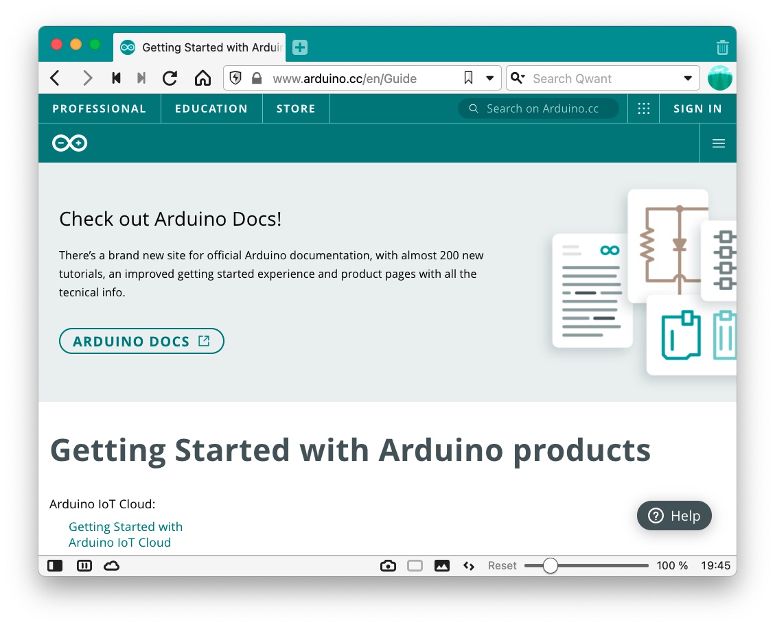
To install the Arduino IDE, download it from the Arduino website, and follow the installation guide linked below.
Arduino IDE download page:
Installation guide:
2. Tools
The Arduino Integrated Development Environment (IDE) contains the following parts:
- an editor for writing sketches
- third party library management
- tools for compiling and uploading sketches
- a serial monitor for viewing debug output
The following describe how to use these tools and the workflow for creating and deploying a sketch.
The following sections describe how to use these tools and the workflow for creating and running a sketch.
3. Connect and Select the Board
3.1. Connect the Board
Connect the target microcontroller board to the computer using an appropriate USB cable.
3.2. Select the Board
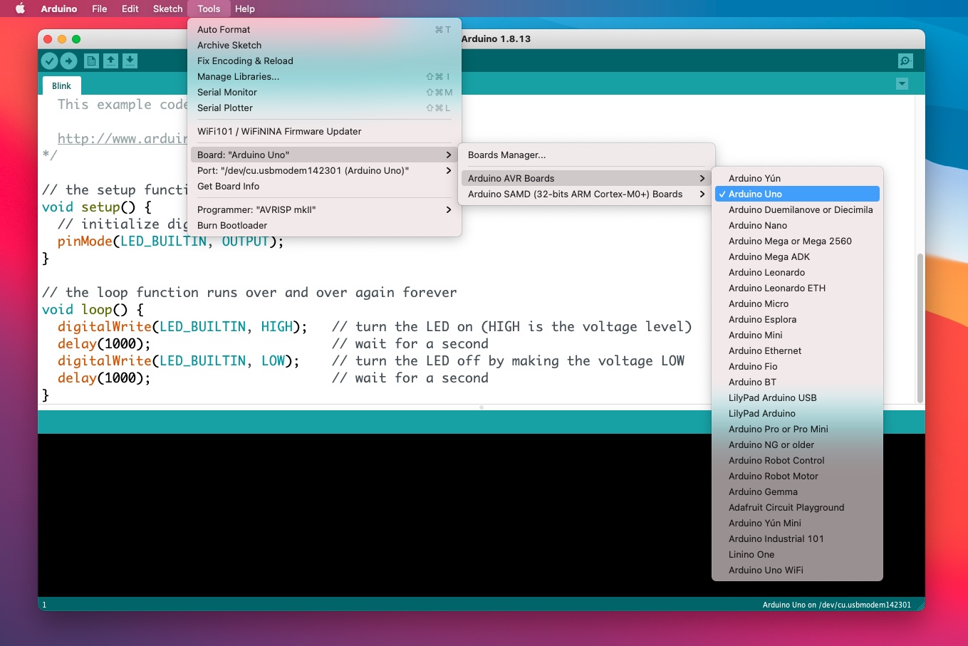
In order to compile and deploy sketches on the target microcontroller, the Arduino IDE needs to know what type of microcontroller is being targeted. Use the Tools→Board menu to select the board.
This screenshot shows how to select the Arduino Uno board:
3.3. Select the Serial Port
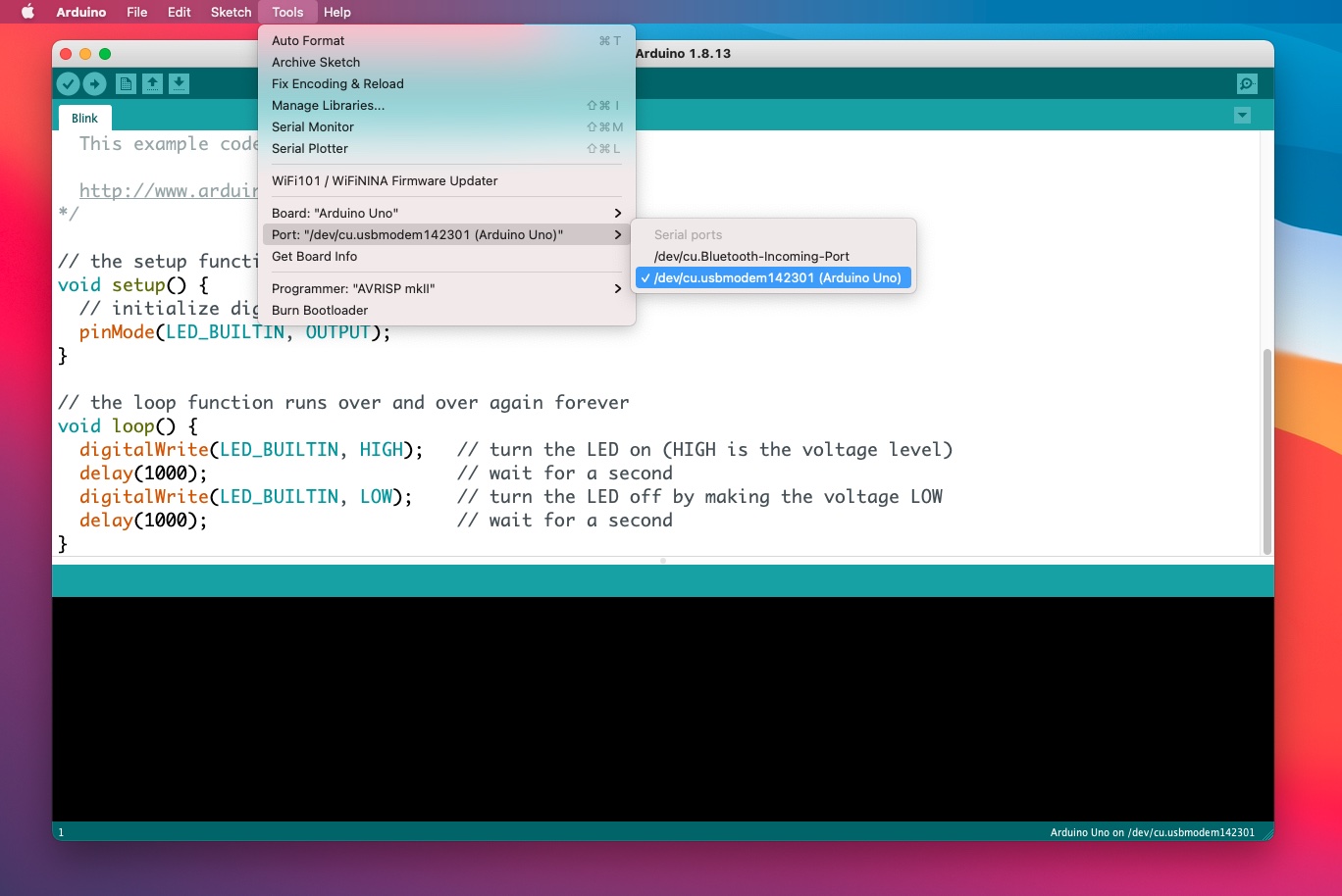
Select what USB port the board is connected to using the Tools→Port menu – the Arduino IDE will identify the board typically in the list.
This screenshot shows how to select the port for the Arduino Uno:
3.4. Linux USB Configuration
On Linux systems, you need to add your user to the dialout group to grant full access to serial USB ports. Open a terminal and enter the following command:
sudo usermod -a -G dialout $USER
Then restart your computer to make changes take effect.
For further instructions, see the Linux USB Configuration guide.
3.5. USB Port Naming Conventions
The USB naming conventions differ based on the operating system used on the computer. On Windows, they use names like COMXX (where XX is the port number); on Mac OSX and Linux they use /dev/ttyXXXX or similar.
Windows tends to create a new port number each time a device is disconnected and re-connected to the computer so it is important to ensure the right port is selected.
If the board is not visible in the ports menu, or if it disappears, it can help to reset the board. In some instances (such as on the Nano 33 BLE), pressing the reset button twice can help to reconnect the board.
4. Board Packages
The default Arduino IDE provides support for boards that use the Atmel Atmega AVR microcontrollers. When using other boards, the Arduino IDE must be updated to include support for the appropriate microcontroller, which will include tools like compilers, linkers and flash programming tools.
When connecting a board to the computer while the Arduino IDE is running, it may detect that the board package has not yet been installed – and it may offer to install it on the computer. In the event this does not happen; the board support can be configured manually using the Tools→Board→Board Manager menu.
4.1. Install the MKR WiFi 1010 Board Package
The RIoT Secure Platform supports the use of the Arduino MKR family of boards for the modem of a FUSION device. This sections describes how to install the package for MKR WiFi 1010 board. Packages for other MKR boards are installed in a similar way.
4.1.1. Automatic install
The first time the MKR WiFi 1010 board is connected, the Arduino IDE should show a dialog offering to install the package for it.
4.1.2. Manual install
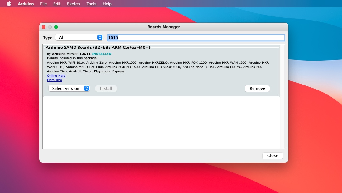
The package can also be selected manually in the menu Tools→Board→Boards Manager.
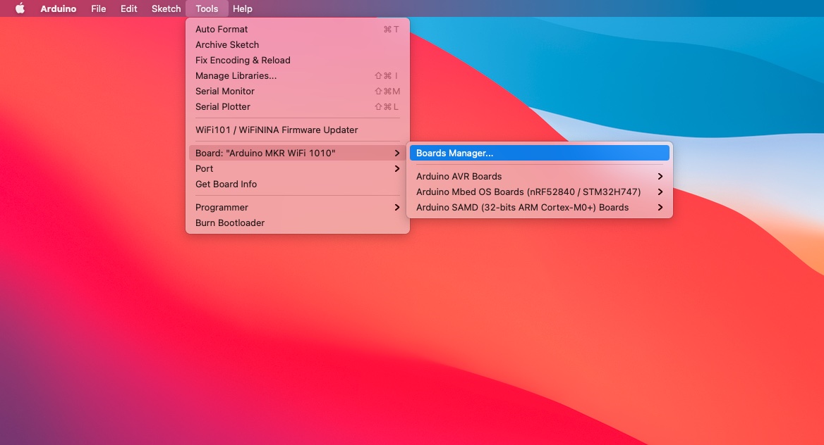
In the dialog window, type 1010 in the search field. This will show the package installer for the MKR WiFi 1010. Move the mouse pointer over the item shown to display an Install button.
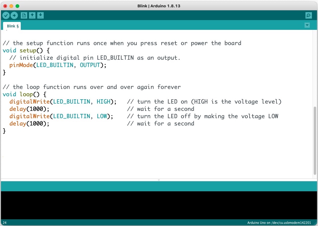
5. Create a Sketch
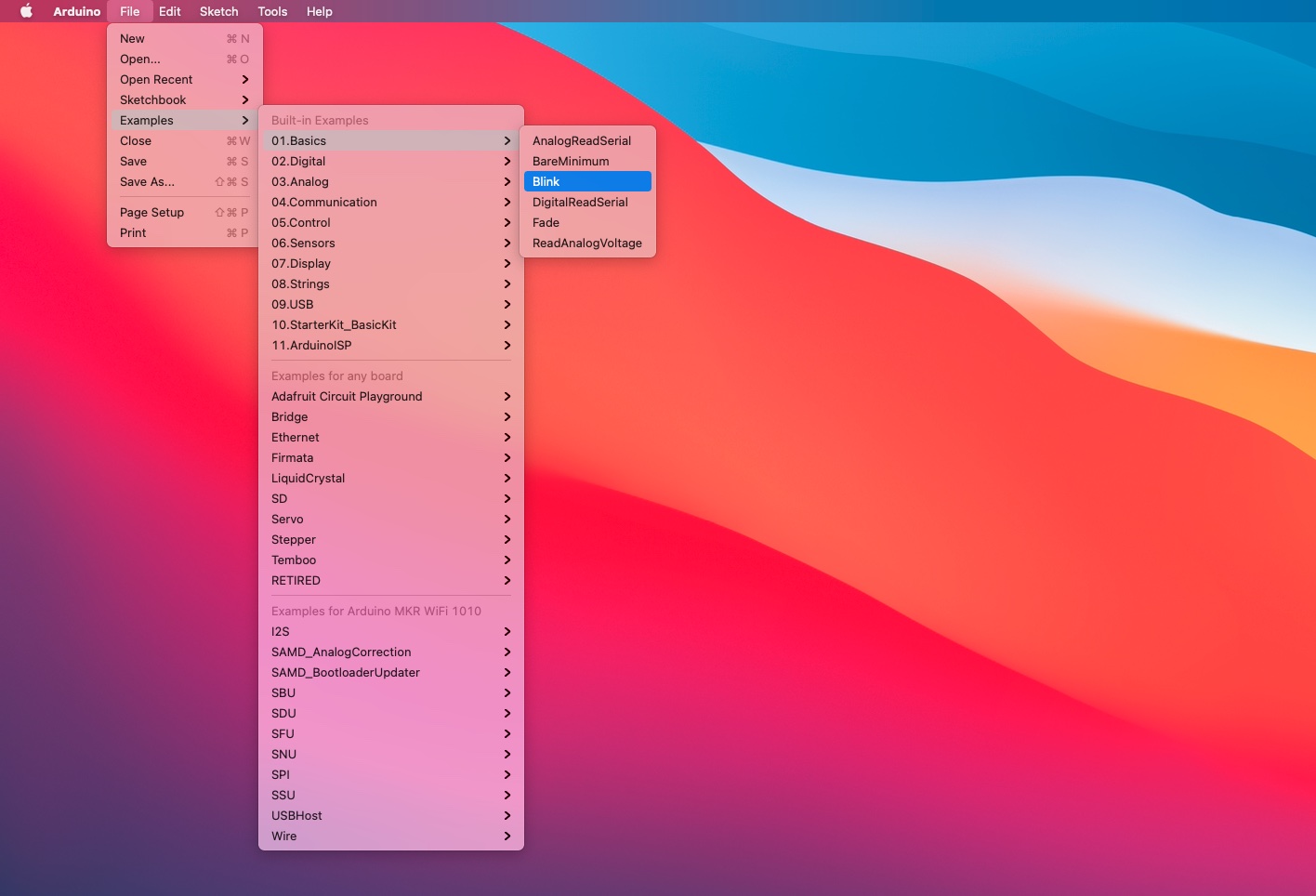
To get started with the Arduino IDE, a number of example sketches exist for each microcontroller board.
This screenshot shows how to select the predefined Blink sketch from the File→Examples→01.Basics menu.
To create a new empty sketch, use the File→New menu item.
It is important to always save any changes made to the sketch; all sketches are saved in the Arduino folder in the default Documents directory on the computer.
6. Compile and Deploy a Sketch
In order to deploy (upload) the sketch to the microcontroller board, it first must be compiled into a firmware file. Once compiled; it can be uploaded over the USB port – that talks to a special bootloader, a small program on the microcontroller board that is responsible for programming the microcontroller. The bootloader is active for a few seconds every time the board is reset.
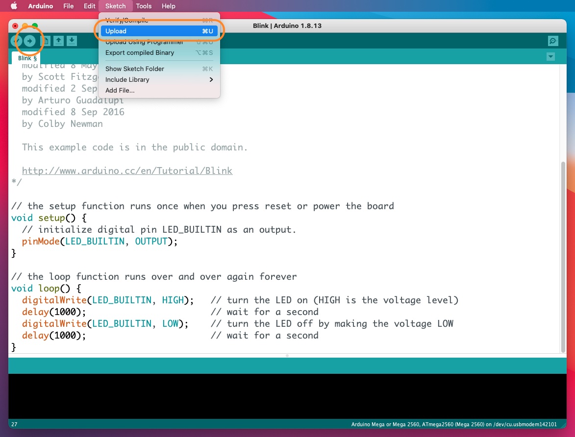
Compile and upload the sketch using the Sketch→Upload menu item. To compile only, use the Sketch→Compile menu item.
The sketch can also be compiled and uploaded using the Upload arrow button in the toolbar, as shown in this screenshot (use one of the options highlighted):
If there are any syntax errors in the sketch, or if there is a problem communicating with the microcontroller board – a series of error messages will be shown in the output panel of the code window (black area). On successful upload, the firmware will start to execute.
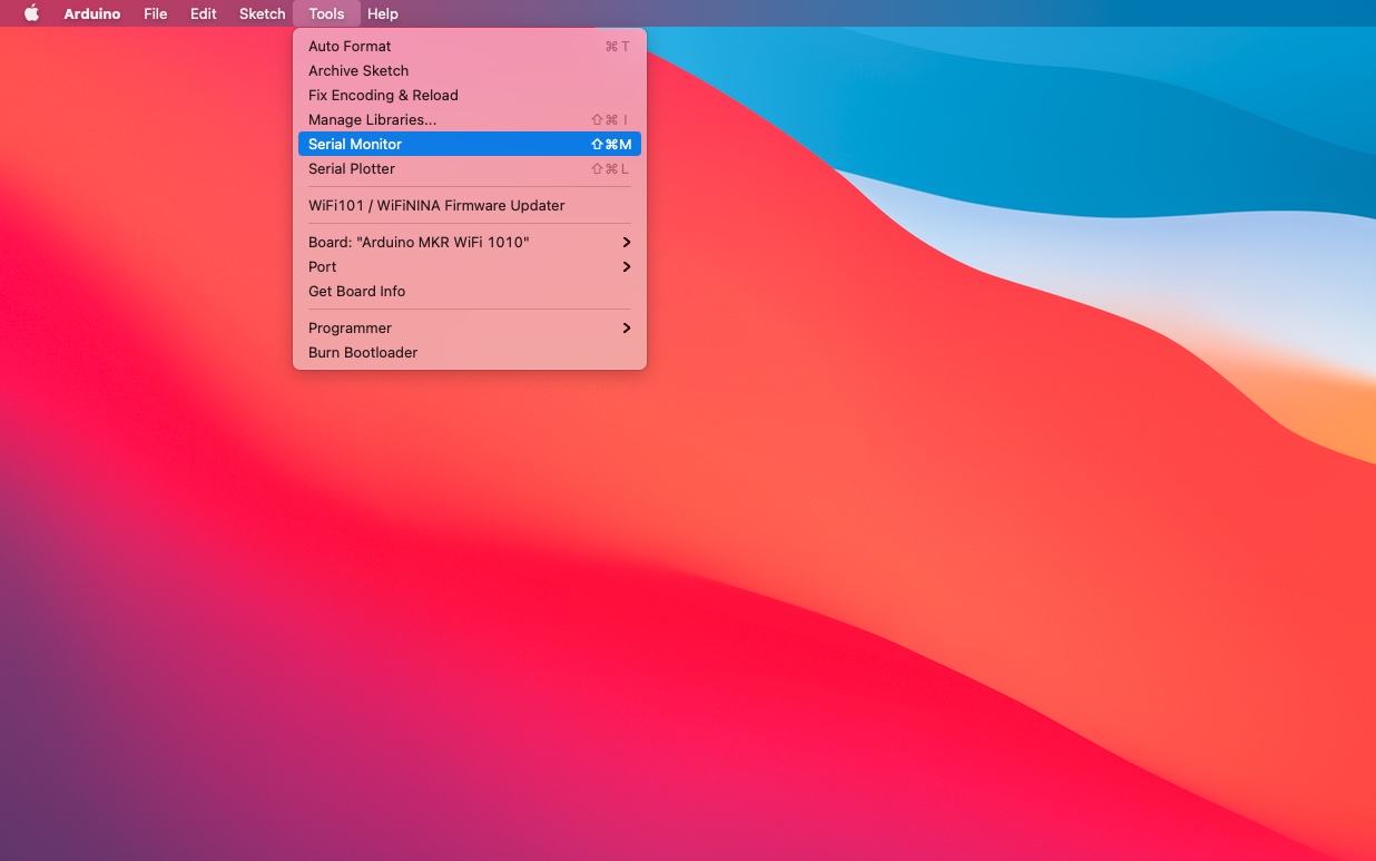
7. Serial Monitor
The Serial Monitor in the Arduino IDE is used to view any serial output, typically used for showing debug messages that are programmed into the sketch. The Serial Monitor will connect to the serial interface of the microcontroller on the currently selected port – the Tools→Port menu will show all connected boards.
Open the Serial Monitor window with the Tools→Serial Monitor menu item.
Select the appropriate baud rate that is defined within the sketch in the bottom toolbar of the Serial Monitor window; by default this is 9,600 or 115,200 baud – with the correct baud rate, data will appear.
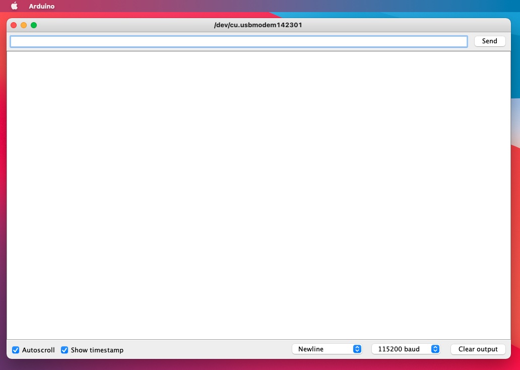
If the baud rate is not appropriately configured, garbage or no data at all will be displayed. Should garbage be displayed, try a baud rate of 9600.
Other useful settings are Autoscroll and Show timestamp, to improve the readability of the output.
Turn Autoscroll on or off depending on if displayed should automatically scroll as new information is received over the USB port. To be able to scroll back in the log while the device is running, turn Autoscroll off.
Turn Show timestamp on to see a timestamp added to each line.