Create Application Firmwares in the Arduino IDE
1. Introduction
This document explains how to create application firmwares (“sketches”) using the Arduino IDE. Compiled firmware files are uploaded to the physical device via the OASIS Cloud.
Good to Know
The physical FUSION board does not need to be connected to the computer when compiling application firmware, as the application firmware is uploaded over-the-air.
It is however important to select the board in the Arduino IDE. This is done in the Tools→Board menu (see detailed instructions below).
Related Documentation
See the guide Export Application Firmware for further details regarding how to export a compile firmware file.Also see the Firmware Over-the-Air Tutorial.
2. Firmware Example Code
Below are basic example sketches for popular application boards supported by the RIoT Secure Platform.
2.1. Arduino Uno R4 WiFi
This section describes how to create a basic Blink sketch for the Arduino Uno R4 WiFi that repeatedly turns the onboard LED on and off.
Select the Board
Begin by selecting the application board in the Arduino IDE. This is the board the code will be compiled for.
-
Open the Arduino IDE.
-
Select the board using the menu option Tools→Board→Arduino UNO R4 Boards→Arduino UNO R4 WiFi.
If the Arduino UNO R4 Boards option is not present in the Tools→Board menu, select the menu command Tools→Board→Boards Manager. Enter uno r4 in the search box, and install the Arduino UNO R4 Boards package.
- The Arduino IDE is now set up to compile sketches for the Arduino UNO R4 WiFi.
Create the Sketch
-
Open the Arduino IDE and create a new sketch using the menu command File→New Sketch.
-
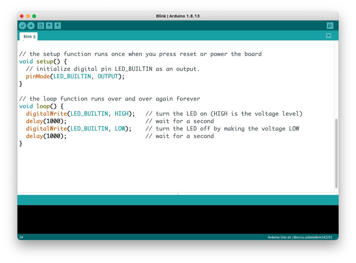
Enter the following code.
// The setup function is called once on initialization
void setup()
{
  // Enable the pin of the built-in LED for output
  pinMode(LED_BUILTIN, OUTPUT);
}

// The loop function is called repeatedly while the sketch is running
void loop()
{
  // Turn LED ON
  digitalWrite(LED_BUILTIN, HIGH);

  // Wait 2000 milliseconds (2 seconds)
  delay(2000);

  // Turn LED OFF
  digitalWrite(LED_BUILTIN, LOW);

  // Wait 2000 milliseconds (2 seconds)
  delay(2000);
}
- Save the sketch.
Note the folder where the sketch is saved - this is where the compiled firmware uploaded to the OASIS Cloud will be saved.
Export the Compiled Sketch
- Compile and export a binary firmware file using the menu command Sketch→Export Compiled Binary. If there are any compilation errors, they will be dsiplayed in the code window.
The compiled sketch will be saved in the folder where the sketch has been saved. If the sketch is named Blink.ino, the exported file will be named:
Blink.ino.hex
This is the file to be uploaded to the OASIS Cloud using the Management Console.
2.2. Arduino Uno
This section describes how to create a basic Blink sketch for the Arduino Uno that repeatedly turns the onboard LED on and off.
Select the Board
Begin by selecting the application board in the Arduino IDE. This is the board the code will be compiled for.
-
Open the Arduino IDE.
-
In the Tools menu, select Tools→Board→Arduino AVR Boards→Arduino Uno
-
The Arduino IDE is now set up to compile sketches for the Arduino Uno.
Create the Sketch
-
Open the Arduino IDE and create a new sketch using the menu command File→New Sketch.
-
Enter the following code.
// The setup function is called once on initialization
void setup()
{
  // Enable the pin of the built-in LED for output
  pinMode(LED_BUILTIN, OUTPUT);
}

// The loop function is called repeatedly while the sketch is running
void loop()
{
  // Turn LED ON
  digitalWrite(LED_BUILTIN, HIGH);

  // Wait 2000 milliseconds (2 seconds)
  delay(2000);

  // Turn LED OFF
  digitalWrite(LED_BUILTIN, LOW);

  // Wait 2000 milliseconds (2 seconds)
  delay(2000);
}
- Save the sketch.
Note the folder where the sketch is saved - this is where the compiled firmware uploaded to the OASIS Cloud will be saved.
Export the Compiled Sketch
- Compile and export a binary firmware file using the menu command Sketch→Export Compiled Binary. If there are any compilation errors, they will be dsiplayed in the code window.
The compiled sketch will be saved in the folder where the sketch has been saved. If the sketch is named Blink.ino, the exported file will be named:
Blink.ino.hex
This is the file to be uploaded to the OASIS Cloud using the Management Console.
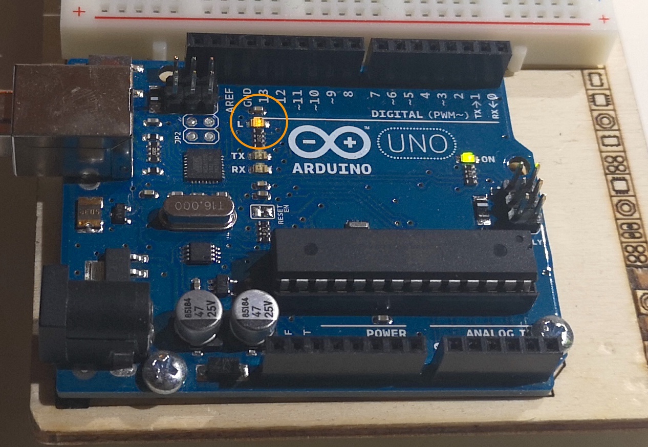
The above sketch will blink small yellow onboard LED of the Arduino Uno.
2.3. Arduino Mega
This section describes how to create a basic Blink sketch for the Arduino Mega that repeatedly turns the onboard LED on and off.
Select the Board
Begin by selecting the application board in the Arduino IDE. This is the board the code will be compiled for.
-
Open the Arduino IDE.
-
In the Tools menu, select Tools→Board→Arduino AVR Boards→Arduino Mega or Mega 2560
-
The Arduino IDE is now set up to compile sketches for the Arduino Mega.
Create the Sketch
-
Open the Arduino IDE and create a new sketch using the menu command File→New Sketch.
-
Enter the following code.
// The setup function is called once on initialization
void setup()
{
  // Enable the pin of the built-in LED for output
  pinMode(LED_BUILTIN, OUTPUT);
}

// The loop function is called repeatedly while the sketch is running
void loop()
{
  // Turn LED ON
  digitalWrite(LED_BUILTIN, HIGH);

  // Wait 2000 milliseconds (2 seconds)
  delay(2000);

  // Turn LED OFF
  digitalWrite(LED_BUILTIN, LOW);

  // Wait 2000 milliseconds (2 seconds)
  delay(2000);
}
- Save the sketch.
Note the folder where the sketch is saved - this is where the compiled firmware uploaded to the OASIS Cloud will be saved.
Export the Compiled Sketch
- Compile and export a binary firmware file using the menu command Sketch→Export Compiled Binary. If there are any compilation errors, they will be dsiplayed in the code window.
The compiled sketch will be saved in the folder where the sketch has been saved. If the sketch is named Blink.ino, the exported file will be named:
Blink.ino.hex
This is the file to be uploaded to the OASIS Cloud using the Management Console.
The above sketch will blink small yellow onboard LED of the Arduino Mega.
2.4. Ingwaz Board
The Ingwaz Board is an industrial production board designed by RIoT Secure AB.
This section shows how to make a basic sketch that outputs data over a TTL/USB cable over an UART serial connection to the Ingwaz Board.
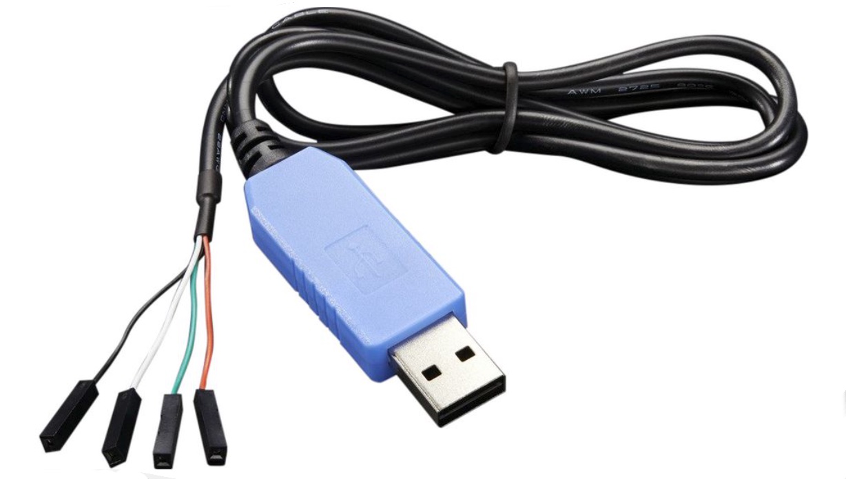
On the Ingwaz Board, pins 12 and 13 are used for serial communication. Use an adapter to connect these pins to the USB-port of the computer, for example the Adafruit USB to TTL Serial Cable shown below.
Select the Board
Begin by selecting the application board in the Arduino IDE. This is the board the code will be compiled for.
-
Open the Arduino IDE.
-
In the Tools menu, select Tools→Board→Arduino AVR Boards→Arduino Mega or Mega 2560
-
The Arduino IDE is now set up to compile sketches for the Ingwaz Board.
Create the Sketch
-
Open the Arduino IDE and create a new sketch using the menu command File→New Sketch.
-
Enter the following code.
// Example application for the Ingwaz board that outputs data
// using UART (Universal Asynchronous Receiver-Transmitter)

#include <SoftwareSerial.h>

// Input (receive) and output (transmit) pins
#define rxPin 12
#define txPin 13

// Create serial (UART) object
SoftwareSerial serial(rxPin, txPin);

// Counter value (used as example data)
int counter = 0;

// The setup function is called once on initialization
void setup()
{
  // Set pins for input and output
  pinMode(rxPin, INPUT);
  pinMode(txPin, OUTPUT);

  // Set baud rate (select matching baud rate in the
  // Serial Monitor in the Arduino IDE)
  serial.begin(115200);

  // Wait a little and output initial message
  delay(1000);
  serial.print("Begin\r\n");
}

// The loop function is called repeatedly while the sketch is running
void loop()
{
  // Output counter value
  serial.print("Counter: ");
  serial.print(counter);
  serial.print("\r\n");

  // Increment counter
  ++ counter;

  // Wait a while before sending next output
  delay(2000);
}
- Save the sketch.
Note the folder where the sketch is saved - this is where the compiled firmware uploaded to the OASIS Cloud will be saved.
Export the Compiled Sketch
- Compile and export a binary firmware file using the menu command Sketch→Export Compiled Binary. If there are any compilation errors, they will be dsiplayed in the code window.
The compiled sketch will be saved in the folder where the sketch has been saved. If the sketch is named Blink.ino, the exported file will be named:
Blink.ino.hex
This is the file to be uploaded to the OASIS Cloud using the Management Console.
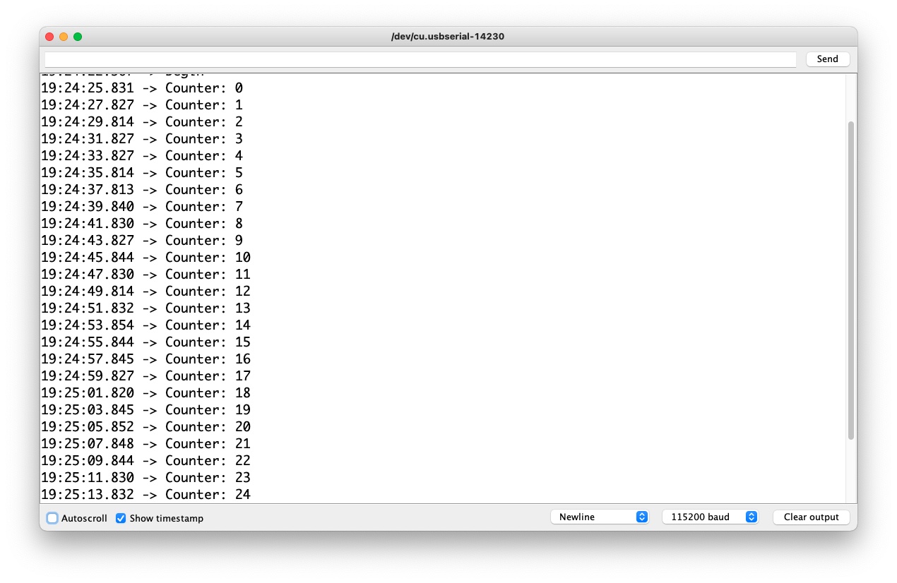
When the above sketch is running, it will output data to the Serial Monitor.
3. Arduino Example Sketches
The Arduino IDE comes with many example sketches that can be experimented with, and be used as an inspiration for coding application firmwares.
The examples can be found under the File→Examples menu.
It is important to select the board in the Tools→Board menu.