FUSION Core Firmware Log
The FUSION Core Firmware Log
The FUSION Core Firmware Log is accessible from the Serial Monitor in the Arduino IDE. This log reports the interaction between a FUSION device and the IoT Server. It is useful for debugging and monitoring.
The communications protocol used between the FUSION Core Firmware and IoT Server is microTLS (μTLS).
The FUSION Core Firmware outputs various debugging information. This can be helpful to not only understand what is going on, but also with the isolation of problems when they happen. The support team may ask for the FUSION Core Firmware Log to assist with any support queries.
1. Serial Monitor
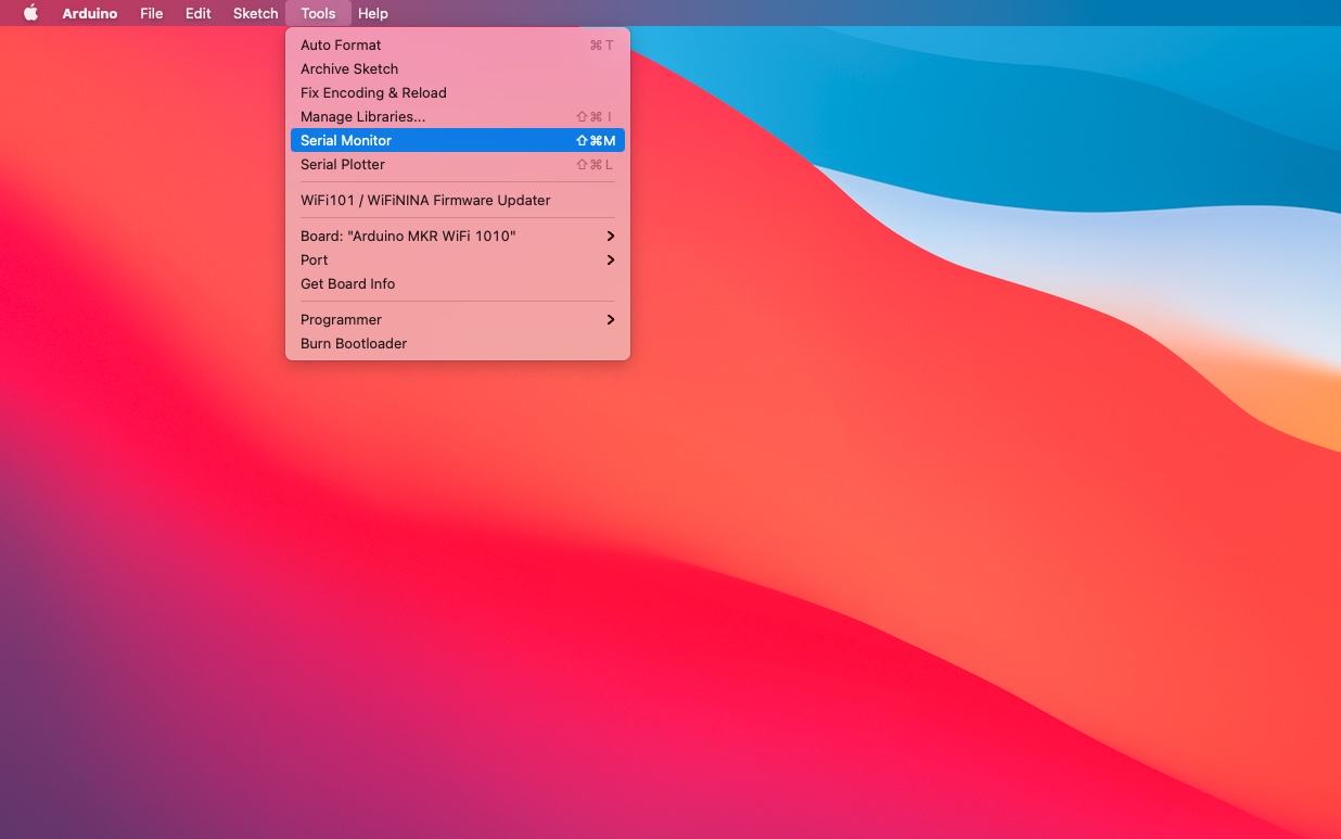
The FUSION Core Firmware log is displayed in the Serial Monitor window within the Arduino IDE.
The FUSION device may be connected to multiple USB ports of the computer, one for the modem microcontroller and the one for the application board microcontroller. The FUSION Core Firmware log is specific to the modem of the FUSION device; the application board may also have its own distinct debugging log exposed.
Use the Tools→Port menu to select the USB port that is associated with the modem. Open the Serial Monitor using the Tools→Serial Monitor menu option and ensure that the baud rate is set to 115200 baud. If configured correctly; device logs should automatically appear in the Serial Monitor window.
Different types of information are presented in the FUSION Core Firmware log, as outlined further on.
To view the FUSION Core Firmware Logs from start up, press the reset button on the modem.
2. Device Startup
This section lists the log entries displayed during the device startup phase.
2.1. Startup Logo
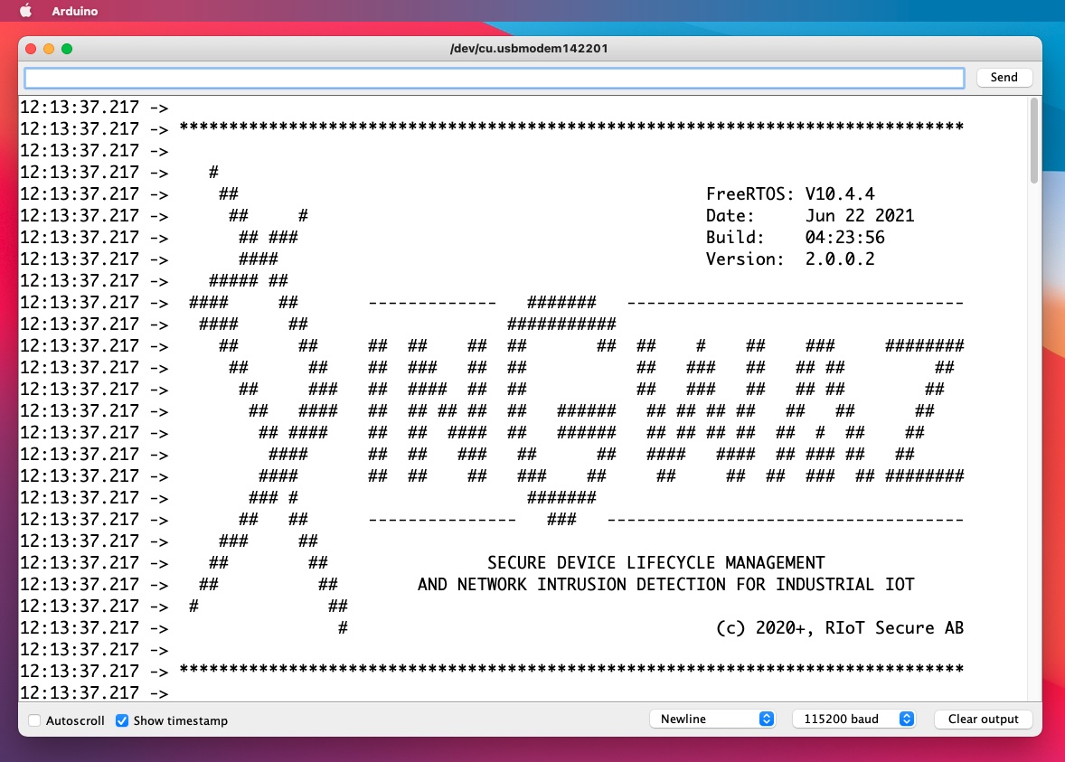
On initial startup or reboot of the modem, the welcome logo, build date and version are shown.
10:33:11.575 -> *******************************************************************************
10:33:11.575 ->
10:33:11.575 -> #
10:33:11.575 -> ## FreeRTOS: V10.4.4
10:33:11.575 -> ## # Date: Jun 22 2021
10:33:11.575 -> ## ### Build: 04:23:56
10:33:11.575 -> #### Version: 2.0.0.2
10:33:11.575 -> ##### ##
10:33:11.575 -> #### ## ------------- ####### ----------------------------------
10:33:11.575 -> #### ## ###########
10:33:11.575 -> ## ## ## ## ## ## ## ## # ## ### ########
10:33:11.575 -> ## ## ## ### ## ## ## ### ## ## ## ##
10:33:11.575 -> ## ### ## #### ## ## ## ### ## ## ## ##
10:33:11.575 -> ## #### ## ## ## ## ## ###### ## ## ## ## ## ## ##
10:33:11.575 -> ## #### ## ## #### ## ###### ## ## ## ## ## # ## ##
10:33:11.575 -> #### ## ## ### ## ## #### #### ## ### ## ##
10:33:11.575 -> #### ## ## ## ### ## ## ## ## ### ## ########
10:33:11.575 -> ### # #######
10:33:11.575 -> ## ## --------------- ### ------------------------------------
10:33:11.575 -> ### ##
10:33:11.575 -> ## ## SECURE DEVICE LIFECYCLE MANAGEMENT
10:33:11.575 -> ## ## AND NETWORK INTRUSION DETECTION FOR INDUSTRIAL IOT
10:33:11.575 -> # ##
10:33:11.575 -> # (c) 2020+, RIoT Secure AB
10:33:11.575 ->
10:33:11.575 -> *******************************************************************************
10:33:11.575 ->
The Hardware Information for the modem is displayed next.
10:33:11.575 -> :: Arduino MKR WiFi 1010
10:33:11.575 ->
10:33:11.575 -> - Atmel SAMD21 Cortex-M0+ @48Mhz
10:33:11.575 -> - 256kb Flash, 32kb RAM
10:33:11.575 -> - UBLOX NINA-W10 (ESP32)
10:33:12.577 -> - Power Management BQ24195
10:33:12.577 -> settings: 4.28V 3.00A 3.50V : disable battery charge (not present)
10:33:12.644 -> - MicroChip ECCx08
10:33:12.644 -> serial: 01 23 FF 8C 0A E3 98 6F EE
10:33:12.644 ->
2.3. Initialization and Health Checks
The system is then initialized; checking the health of various components at the same time.
10:33:12.644 -> :: RAM available: 1735 bytes
10:33:12.644 -> :: SYS vNopDelay: PASS => 1.00
10:33:12.716 -> :: SYS integrity (BOOT_USB): sys: 0x97D143C1 new: 0x97D143C1
10:33:12.749 -> :: initialize MEM:
10:33:12.749 -> * initialize SD: DONE
10:33:12.749 -> ? SD health check => FAIL
10:33:12.749 -> - SD card format => SUCCESS
10:33:26.523 -> * initialize SD: DONE
10:33:26.559 -> ? SD health check => PASS
10:33:31.492 -> - card: SDHC
10:33:31.492 -> - volume: FAT32
10:33:31.492 -> - product: SD SC16G (A6203AB7)
10:33:31.492 -> - size: 15931539456 bytes
10:33:31.492 -> - free: 15923085312 bytes
10:33:31.492 ->
10:33:31.492 -> SD:\
10:33:31.492 -> 2021-08-19 08:32 4 RIoT.XXX
10:33:31.492 ->
10:33:31.492 -> * initialize SPIM: DONE
10:33:31.492 -> ? flash health check => PASS
10:33:31.492 -> - chip: EF 40 15
10:33:31.492 -> - serial: E6 69 AC 82 8B 88 48 2F
10:33:31.492 -> - size: 2097152 bytes
10:33:36.979 -> :: initialize MEM: done
10:33:36.979 -> :: initialize WDT: done
10:33:36.979 -> :: initialize SYS: done
10:33:36.979 -> :: initialize GPS: ....... fail
10:33:43.960 -> :: initialize EXT:
10:33:43.960 -> * initialize ISP: DONE
10:33:43.960 -> * initialize SERx: done
10:33:43.960 -> :: initialize EXT: done
10:33:43.960 -> :: initialize NET:
10:33:44.760 -> * initialize uTLS: DONE
10:33:44.760 -> - uTLS GUID: 52 4A 6F 57 4D 4B 52 77 01 23 FF 8C 0A E3 98 6F
10:33:44.760 -> :: initialize NET: done
The FUSION Core Firmware will initialize the microSD card during the health check to ensure that the file system is correctly formatted - ensuring that the microSD card and file operations are reliable and robust. The GPS module was not present (hence fail) in this specific FUSION device hardware configuration.
2.4. Microcontroller Detection
An important connection between the modem microcontroller and the application microcontroller is the multi microcontroller ISP (In System Programming) interface - depending on the microcontrollers used, a connection to specific pins of the target microcontrollers exists, as used by typical debugging hardware (SWD, ISCP, JTAG et al).
Any microcontrollers that exist on the application board of the FUSION device will be detected and shown.
10:33:44.760 -> :: micro-controllers:
10:33:44.760 -> * detecting micro-controller #1
10:33:44.798 -> sys_isp_isr() : connected
10:33:44.798 -> :: initializing ISP programming:
10:33:45.121 -> > found DAP-SWD:
10:33:45.121 -> - SW-DP IDCODE 0x2BA01477
10:33:45.121 -> - ver: 2 partno: 0xBA01 designer: 0x023B (ARM Limited)
10:33:45.121 -> :: initializing ISP programming: done
10:33:45.155 -> > found device:
10:33:45.155 -> - HWID: 00 05 28 40
10:33:45.155 -> - CPU Family: ARM Cortex M4 r0p1 (little-endian)
10:33:45.155 -> - CPU: nRF52840 rev: AAD0
10:33:45.155 -> - Flash (pages): 1048576 (256)
10:33:45.155 -> - PageSize: 4096
10:33:45.155 -> - Memory (SRAM): 262144
10:33:45.155 -> :: terminating ISP programming
Above, an Arduino BLE 33 Sense using the Nordic Semiconductor nRF52840 microcontroller was found.
3. Communication
microTLS (μTLS) is the protocol used for communication between the FUSION Core Firmware and IoT Server. It is a simple handshake based protocol built on top of TCP/IP
The microTLS (μTLS) protocol allows any unknown FUSION Core Firmware to connect anonymously, gain trust by identifying itself and encrypting a token, then exchange encryption keys to allow ongoing secure communications between the FUSION Core Firmware and the IoT Server.
An important design of the microTLS (μTLS) protocol is that only basic headers are public (status, checksum, length) - the remainder of the data is encapsulated in an encrypted packet that not only must pass a simple checksum check, but also an integrity check - to ensure that the decrypted contents have not changed.
The following are log entries related to the communications protocol.
3.1. Establish Communication
Connecting to the Internet (or private network) is a essential operation of the FUSION Core Firmware.
Depending on the communications protocol used in the modem (WiFi, 3G, NB-IoT) - the underlying module responsible for communication is initialized and the appropriate configuration settings to acquire an IP address are performed - such as connection to an SSID (WiFi) or APN (3G, NB-IoT).
10:33:46.174 -> WiFi FW: 1.2.3
10:33:46.244 -> WiFi MAC: F0:08:D1:CE:E5:60
10:33:46.354 -> :: WiFi - connecting to SSID
10:33:46.862 -> ..........
Once an IP address has been obtained, it is assumed to be connected to the Internet (or private network) and the FUSION Core Firmware will attempt to communicate with the IoT Server using the microTLS (μTLS) protocol. Periodically; the status of the network connection will be presented.
10:33:49.265 -> SSID: MY WIFI NAME
10:33:49.271 -> BSSID: B0:EB:57:39:3F:47
10:33:49.384 -> RSSI: -68
10:33:49.720 -> IP addr: 192.168.43.196
10:33:49.720 -> subnet: 255.255.255.0
10:33:49.720 -> gateway: 192.168.43.1
A communication channel specific for sending messages in both directions between the modem microcontroller and the application board microcontroller exists using an internal UART serial connection.
10:33:46.426 -> :: initializing serial communications @ 57600
Information exchanged is relayed to and from the IoT Server mimicking a secure VPN like tunnel.
3.2. Token Request
The FUSION Core Firmware must first anonymously connect to the IoT Server and request a token.
10:33:49.720 -> :: connecting to server/token: DONE
10:33:50.515 -> netdbg: 4338 : seq = 00 : req = 1 : avail = 40
10:33:50.838 -> netdbg: 4641 : seq = 01 : req = 3 : avail = 39
10:33:50.838 -> netdbg: 4641 : seq = 02 : req = 36 : avail = 36
10:33:50.838 -> netdbg: 4654 : seq = 03 : req = 32 : avail = 32
10:33:50.838 ->
10:33:50.838 -> :: disconnecting
10:33:50.838 ->
10:33:50.838 -> code = 0x20
10:33:50.838 -> cs = 0x19 && 0x19 (PASS)
10:33:50.838 -> len = 36 bytes
10:33:50.838 -> ts = 1629362030
10:33:50.838 -> token = UJEMNNVBIDKRZJTPUBQHUQQTCPMEODZY
The token itself, isn’t anything special - it is simply a series of random uppercase ASCII characters.
3.3. Establishing a Session
The FUSION Core Firmware must first establish trust with the IoT Server.
An important design of the platform requires that the FUSION device be pre-configured in the system, in which a pre-shared encryption key will be created and defined. The FUSION Core Firmware must encrypt the token it received using pre-shared encryption keys provided and then attempt to establish a session.
10:33:51.018 -> :: connecting to server/session: DONE
10:33:51.769 -> netdbg: 5585 : seq = 00 : req = 1 : avail = 76
10:33:52.089 -> netdbg: 5888 : seq = 01 : req = 3 : avail = 75
10:33:52.089 -> netdbg: 5888 : seq = 02 : req = 72 : avail = 72
10:33:52.089 -> netdbg: 5895 : seq = 03 : req = 48 : avail = 48
10:33:52.089 -> netdbg: 5900 : seq = 04 : req = 32 : avail = 32
10:33:52.126 ->
10:33:52.126 -> :: disconnecting
10:33:52.126 ->
10:33:52.126 -> code = 0x20
10:33:52.126 -> cs = 0x41 && 0x41 (PASS)
10:33:52.126 -> len = 72 bytes
10:33:52.126 -> ts = 1629362031
10:33:52.126 -> session = 08 8D D4 55 52 CD DD E0 48 AC 65 73 54 75 8E DC
10:33:52.164 -> itg = 0x05FDB671 && 0x05FDB671 (PASS)
10:33:52.164 -> aes_xch = B0 94 DF 33 B1 57 B7 EC 1B E2 41 25 C0 32 FC 0B
On receival of the request; the IoT Server is able to uniquely identify the FUSION Core Firmware and use the corresponding encryption keys to decrypt the message that is sent. If the decrypted contents match the token that was originally issued; then the FUSION Core Firmware can be trusted and a unique session encryption key is provided for exchange of information and firmware updates.
Sessions are also subject to TTL (Time To Live) rules; to prevent the FUSION Core Firmware from having to repeat the communications process to re-establish trust each time it communicates with the IoT Server. The TTL period is managed and configured in the IoT Server.
The FUSION Core Firmware and the IoT Server now communicate over a secure, encrypted channel.
10:33:52.715 -> :: connecting to server/exchange: DONE
10:33:53.319 -> netdbg: 7149 : seq = 00 : req = 1 : avail = 44
10:33:53.636 -> netdbg: 7449 : seq = 01 : req = 3 : avail = 43
10:33:53.636 -> netdbg: 7449 : seq = 02 : req = 40 : avail = 40
10:33:53.636 -> netdbg: 7455 : seq = 03 : req = 32 : avail = 32
10:33:53.636 -> netdbg: 7460 : seq = 04 : req = 16 : avail = 16
10:33:53.669 ->
10:33:53.669 -> :: disconnecting
10:33:53.669 ->
10:33:53.669 -> code = 0x20
10:33:53.669 -> cs = 0xB6 && 0xB6 (PASS)
10:33:53.669 -> len = 40 bytes
10:33:53.669 -> ts = 1629362033
10:33:53.669 -> itg = 0x99F6E95E && 0x99F6E95E (PASS)
The exchange of information allows the FUSION Core Firmware to report its current health status and send data from the application board microcontrollers to the IoT Server for relaying to the Customer Cloud.
The IoT Server may also respond with specific messages (configuration, firmware updates available) and also receive data from the customer IoT cloud for relaying to the application board microcontrollers.
4. Firmware OTA (Over The Air)
The selection of firmware used on the FUSION device is managed within the Management Console.
When the FUSION Core Firmware reports currently installed firmware versions; they are compared against what is configured. If a firmware update is available; a firmware update command is issued. Depending on which microcontroller on the FUSION device needs to be updated, different commands are issued.
-
COREFW
The FUSION Core Firmware on the modem
-
APPLFW0, APPLFW1, APPLFW2 or APPLFW3
The specified microcontroller (a maximum of four are supported) on the application board
Deploying a firmware includes a few logical steps - which includes downloading and saving the firmware to the microSD memory card, decompressing if it has been compressed, checking the firmware is valid, re-programming the microcontroller and then verifying that the re-programming was successful.
The majority of firmware updates will be specific to the application board microcontroller firmware.
4.1. Downloading Firmware
The FUSION Core Firmware connects to the IoT Server responsible for the delivery of firmware updates.
The amount of time it takes to download the firmware is dependent not only on the speed of the network but also on the size of the firmware - which can vary drastically in size depending on the type of micro- controller, the underlying operating system, programming languages and libraries utilized in the firmware.
10:33:53.851 -> :: connecting to server/firmware_appl: DONE
10:33:54.867 -> netdbg: 8672 : seq = 00 : req = 1 : avail = 5440
10:33:55.191 -> netdbg: 9026 : seq = 01 : req = 5 : avail = 5439
10:33:55.367 -> netdbg: 9177 : seq = 02 : req = 116428 : avail = 5434
10:33:55.513 -> netdbg: 9346 : seq = 03 : req = 116416 : avail = 5726
10:33:55.694 -> netdbg: 9497 : seq = 04 : req = 116400 : avail = 5710
10:33:56.337 -> netdbg: 10146 : seq = 04 : req = 116144 : avail = 5454
10:33:56.993 -> netdbg: 10806 : seq = 04 : req = 115888 : avail = 5198
10:33:57.632 -> netdbg: 11454 : seq = 04 : req = 115632 : avail = 4942
10:33:58.274 -> netdbg: 12097 : seq = 04 : req = 115376 : avail = 4686
10:33:58.920 -> netdbg: 12745 : seq = 04 : req = 115120 : avail = 5960
10:33:59.564 -> netdbg: 13389 : seq = 04 : req = 114864 : avail = 5704
10:34:00.227 -> netdbg: 14032 : seq = 04 : req = 114608 : avail = 5448
...
10:38:51.326 -> netdbg: 305233 : seq = 04 : req = 2736 : avail = 2736
10:38:51.972 -> netdbg: 305876 : seq = 04 : req = 2480 : avail = 2480
10:38:52.622 -> netdbg: 306511 : seq = 04 : req = 2224 : avail = 2224
10:38:53.272 -> netdbg: 307168 : seq = 04 : req = 1968 : avail = 1968
10:38:53.902 -> netdbg: 307813 : seq = 04 : req = 1712 : avail = 1712
10:38:54.568 -> netdbg: 308457 : seq = 04 : req = 1456 : avail = 1456
10:38:55.185 -> netdbg: 309101 : seq = 04 : req = 1200 : avail = 1200
10:38:55.877 -> netdbg: 309777 : seq = 04 : req = 944 : avail = 944
10:38:56.528 -> netdbg: 310420 : seq = 04 : req = 688 : avail = 688
10:38:57.182 -> netdbg: 311069 : seq = 04 : req = 432 : avail = 432
10:38:57.800 -> netdbg: 311713 : seq = 04 : req = 176 : avail = 176
10:38:58.303 ->
10:38:58.303 -> :: disconnecting
10:38:58.303 ->
10:38:58.303 -> code = 0x20
10:38:58.303 -> cs = 0xEB && 0xEB (PASS)
10:38:58.303 -> len = 116428 bytes
10:38:58.303 -> ts = 1629362034
10:38:58.303 -> session = 08 8D D4 55 52 CD DD E0 48 AC 65 73 54 75 8E DC
10:38:58.339 -> itg = 0xDFD034D5 && 0xDFD034D5 (PASS)
10:38:58.339 -> v(appl) = 01 01 00 05
In this case, the firmware was 116,428 bytes in size and took almost 3 minutes over a WiFi network.
Delivery of the firmware contents is also encapsulated in an encrypted packet, similar to how the exchange of information is performed. Any additional information, such as the firmware version v(appl) is also provided so the FUSION Core Firmware can keep an internal record of various firmware installed.
4.2. Decompressing the Firmware
The IoT Server will utilize compression of the firmware if it is possible as it will reduce transfer time.
10:38:58.414 -> :: decompressing firmware (appl)
10:38:58.414 ->
10:38:58.450 -> - codec: HUFF
10:39:00.448 -> - original size: 243723 bytes
10:39:00.448 -> - compress size: 116378 bytes
10:39:00.448 -> - compress ratio: 47.7%
10:39:01.284 -> - data integrity: 0x88C5A19B && 0x88C5A19B (PASS)
10:39:01.284 -> * success
The download was compressed using the HUFF (Huffman Encoding) algorithm - which was reduced to over half its size. Once decompressed; the firmware is actually 243,723 bytes. It also has its own integrity check to ensure no data was lost in the transmission or compression.
4.3. microcontroller Programming
In order to reprogram the requested microcontroller on the application board; the FUSION Core Firmware must enter the In System Programming (ISP) mode where it can check the microcontroller is actually compatible for re-programming.
10:39:01.284 -> :: disabling serial communications
10:39:01.284 ->
10:39:01.284 -> :: performing firmware (appl) update
10:39:01.284 ->
10:39:01.284 -> :: initializing ISP programming:
10:39:01.615 -> > found DAP-SWD:
10:39:01.615 -> - SW-DP IDCODE 0x2BA01477
10:39:01.615 -> - ver: 2 partno: 0xBA01 designer: 0x023B (ARM Limited)
10:39:01.650 -> :: initializing ISP programming: done
10:39:01.650 -> > found device:
10:39:01.650 -> - HWID: 00 05 28 40
10:39:01.650 -> - CPU Family: ARM Cortex M4 r0p1 (little-endian)
10:39:01.650 -> - CPU: nRF52840 rev: AAD0
10:39:01.650 -> - Flash (pages): 1048576 (256)
10:39:01.650 -> - PageSize: 4096
10:39:01.650 -> - Memory (SRAM): 262144
The internal UART serial connection with the microcontroller on the modem is disconnected.
4.4. Checking Firmware
The firmware is then checked; to ensure no problem will occur while programming the microcontroller.
10:39:01.650 -> :: checking firmware
10:39:01.650 -> :100000000000042089940000C194000055530000B2
10:39:01.650 -> :10001000C594000061530000675300000000000019
10:39:01.650 -> :10002000000000000000000000000000B56B0000B0
10:39:01.650 -> :10003000CD940000000000004D6C00005D6C0000DD
10:39:01.650 -> :10004000A1CC000039470000D3940000D3940000F5
10:39:01.650 -> :10005000D3940000D3940000D3940000D394000004
10:39:01.650 -> :10006000D3940000D3940000D3940000D3940000F4
10:39:01.650 -> :10007000D394000035CE0000D39400005147000017
10:39:01.650 -> :10008000D3940000D3940000D3940000D3940000D4
10:39:01.650 -> :10009000D3940000D3940000D3940000D3940000C4
10:39:01.650 -> :1000A000D3940000D3940000D3940000D3940000B4
10:39:01.650 -> :1000B000D3940000D3940000000000000000000072
10:39:01.650 -> :1000C000D3940000D3940000D3940000D394000094
10:39:01.650 -> :1000D000D3940000D3940000D3940000D394000084
10:39:01.650 -> :1000E000D3940000D3940000D394000000000000DB
...
10:39:04.672 -> :1051C000340F00203C0F00203C0F0020440F002033
10:39:04.672 -> :1051D000440F00204C0F00204C0F0020540F0020E3
10:39:04.672 -> :1051E000540F00205C0F00205C0F0020640F002093
10:39:04.672 -> :1051F000640F00206C0F00206C0F0020740F002043
10:39:04.672 -> :10520000740F00207C0F00207C0F0020FFFFFFFFA9
10:39:04.672 -> :10521000000002000000000025010000450500001C
10:39:04.672 -> :10522000D11700006D1800007D190000F146000044
10:39:04.672 -> :105230002547000000000000010100000000000000
10:39:04.672 -> :10524000000000000000000000000000000000005E
10:39:04.672 -> :10525000000000000000000000000000C5B20000D7
10:39:04.672 -> :08526000000000000000000046
10:39:04.672 -> :0400000300009489DC
10:39:04.672 -> :00000001FF
10:39:04.672 -> - lines: 5419
10:39:04.672 -> - addressLo: 0x00000000
10:39:04.672 -> - addressHi: 0x00015267
10:39:04.672 -> - bytesWritten: 0x00015268 (86632)
10:39:04.672 ->
10:39:04.672 -> * success
All application board microcontrollers firmware is provided in the Intel HEX format, an industry accepted and commonly used delivery format for microcontrollers as it allows for programming distinct memory ranges and internal data validation (checksum) to ensure the data provided hasn’t been tampered with.
The majority of development environments can export the firmware in this format or be converted easily.
4.5. Writing Firmware
The process of writing firmware involves first erasing the firmware, then re-programming the firmware.
10:39:04.672 -> :: erasing firmware
10:39:04.854 -> :: success
10:39:04.854 ->
10:39:04.854 -> :: writing firmware
10:39:04.854 -> ................................................................................
10:39:04.924 -> ................................................................................
10:39:04.962 -> ................................................................................
10:39:04.999 -> ................................................................................
10:39:05.474 -> ................................................................................
10:39:05.546 -> ................................................................................
10:39:05.583 -> ................................................................................
10:39:06.055 -> .............................................................
...
10:39:15.642 -> ................................................................................
10:39:16.112 -> ................................................................................
10:39:16.183 -> ................................................................................
10:39:16.218 -> ................................................................................
10:39:16.256 -> ................................................................................
10:39:16.727 -> ................................................................................
10:39:16.802 -> ................................................................................
10:39:16.837 -> ...........................................................
10:39:17.740 -> * success
4.6. Verifying Firmware
The final stage of the microcontroller firmware update is to actually verify what was written.
10:39:17.740 -> :: verifying firmware
10:39:17.740 -> ................................................................................
10:39:18.171 -> ................................................................................
10:39:18.210 -> ................................................................................
10:39:18.284 -> ................................................................................
10:39:18.696 -> ................................................................................
10:39:18.734 -> ................................................................................
10:39:18.807 -> ................................................................................
10:39:19.214 -> ................................................................................
10:39:19.250 -> ................................................................................
10:39:19.326 ->
...
10:39:27.670 -> ................................................................................
10:39:27.745 -> ................................................................................
10:39:28.157 -> ................................................................................
10:39:28.195 -> ................................................................................
10:39:28.275 -> ................................................................................
10:39:28.308 -> ................................................................................
10:39:28.721 -> ................................................................................
10:39:28.757 -> ................................................................................
10:39:28.833 -> ...........................................................
10:39:29.207 -> * success
10:39:29.207 ->
10:39:29.207 -> :: terminating ISP programming
After this is complete, the In System Programming mode is terminated and the microcontroller is reset.
10:39:30.234 -> :: initializing serial communications @ 57600
The internal UART serial connection for sending messages in both directions between the modem microcontroller and the application board microcontroller is re-established and the task is complete.
10:39:30.958 -> :: connecting to server/exchange: DONE
10:39:31.711 -> netdbg: 345561 : seq = 00 : req = 1 : avail = 44
10:39:32.007 -> netdbg: 345863 : seq = 01 : req = 3 : avail = 43
10:39:32.007 -> netdbg: 345863 : seq = 02 : req = 40 : avail = 40
10:39:32.045 -> netdbg: 345876 : seq = 03 : req = 32 : avail = 32
10:39:32.045 -> netdbg: 345881 : seq = 04 : req = 16 : avail = 16
10:39:32.082 ->
10:39:32.082 -> :: disconnecting
10:39:32.082 ->
10:39:32.082 -> code = 0x20
10:39:32.082 -> cs = 0x4D && 0x4D (PASS)
10:39:32.082 -> len = 40 bytes
10:39:32.082 -> ts = 1629362371
10:39:32.082 -> itg = 0xE6242238 && 0xE6242238 (PASS)
10:39:32.515 ->
10:39:32.515 -> :: connecting to server/exchange: DONE
10:39:33.133 -> netdbg: 346995 : seq = 00 : req = 1 : avail = 44
10:39:33.457 -> netdbg: 347297 : seq = 01 : req = 3 : avail = 43
10:39:33.457 -> netdbg: 347297 : seq = 02 : req = 40 : avail = 40
10:39:33.457 -> netdbg: 347310 : seq = 03 : req = 32 : avail = 32
10:39:33.457 -> netdbg: 347315 : seq = 04 : req = 16 : avail = 16
10:39:33.491 ->
10:39:33.491 -> :: disconnecting
10:39:33.491 ->
10:39:33.491 -> code = 0x20
10:39:33.491 -> cs = 0xE8 && 0xE8 (PASS)
10:39:33.491 -> len = 40 bytes
10:39:33.491 -> ts = 1629362373
10:39:33.491 -> itg = 0xE6242238 && 0xE6242238 (PASS)
The FUSION Core Firmware then reverts to the normal communication process with the IoT Server.