Serial Debugging
1. Introduction
This document explains how to use serial communication to output data from application firmwares. This can be very useful for debugging, testing, and diagnostics when developling embedded application firmware.
In many cases, serial communication is straightforward if the microcontroller provides serial over USB. This is for example the case when using an Arduino Uno or an Arduino Mega with the RIoT FUSION board. In this case, one can simply plug a USB cable into the application board and connect it to the computer.
However, other devices do not provide a port for serial communication over USB. This is the case for the Arduino Uno R4 WiFi. On an Uno R4 WiFi configured for the RIoT Secure Platform, the USB port connects to the ESP32 networking microcontroller, and not to the Renesas application microcontroller.
For the Arduino Uno R4 WiFi, as well as other boards, we can use a USB to Serial adapter cable for this purpose. An adapter cable has a USB connector at one end, and pin connectors at the other end. By connecting the pin wires to the Uno R4, serial communication can be achieved.
2. Using a Serial Adapter Cable
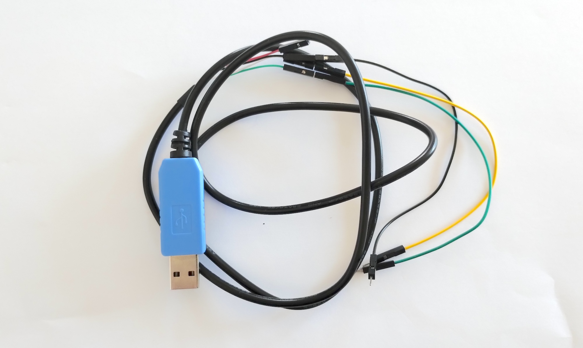
An example of a serial adapter cable is the Adafruit USB to TTL Serial Cable, which is shown below.
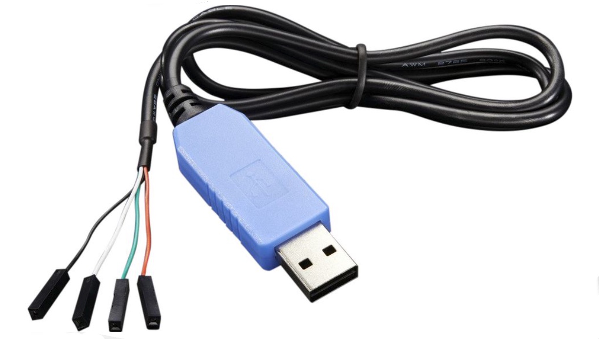
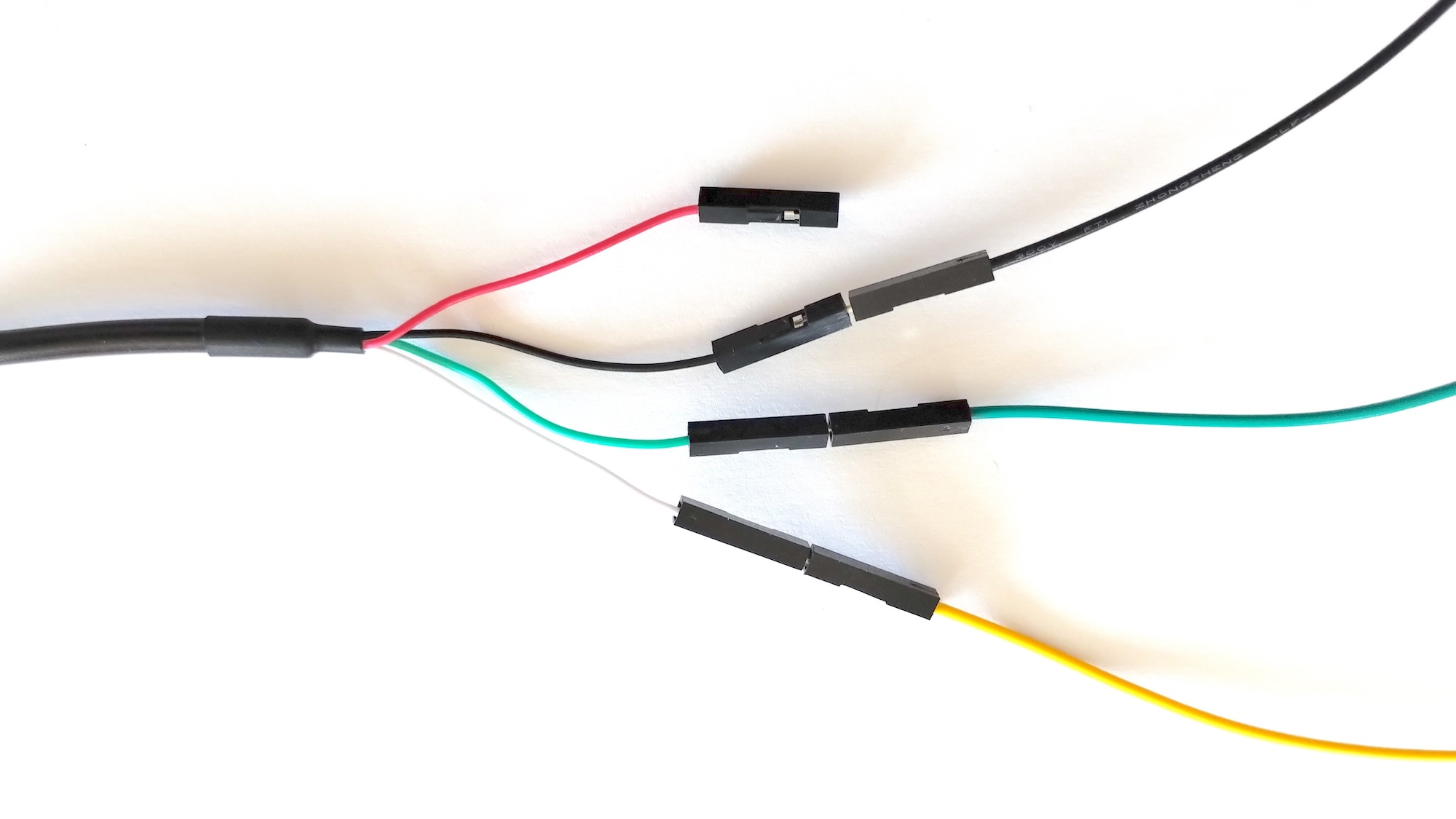
2.1. Wire Colors
A serial adapter cable have wires that connect to pins. These wires have different colors.
Typically, the colors are as follows (check the documentation for your cable):
| Wire | Function |
|---|---|
| Black | Ground - connect to GND pin |
| Green | TX - connect to the RX pin on the board |
| White | RX - connect to the TX pin on the board |
| Red | Power +5V (not needed in our case, do not connect) |
2.2. How to Connect the Adapter Cable
Connect the pins of the serial adapter cable to the board as follows:
| Wire | PIN |
|---|---|
| Black | Connect to the GND pin on the board |
| Green | Connect to the RX (input) pin on the board |
| White | Connect to the TX (output) pin on the board |
| Red | Do not connect the red wire |
The GND pin is labelled “GND” on the board.
The pin numbers for RX and TX are defined in the program code.
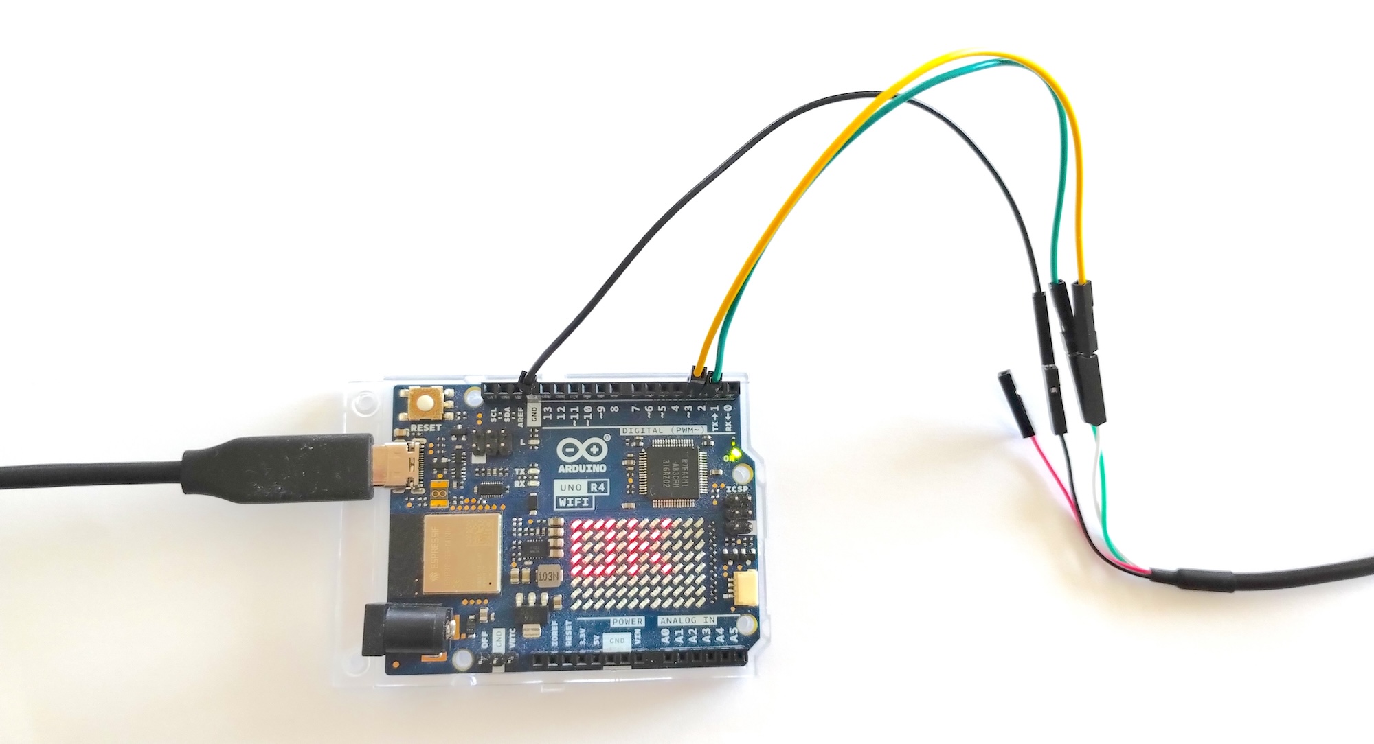
Here is an example of an Arduino Uno WiFi with wires connected to GND, Pin 2, and Pin 3 (in this example the yellow wire is attached to white on the adapter cable):
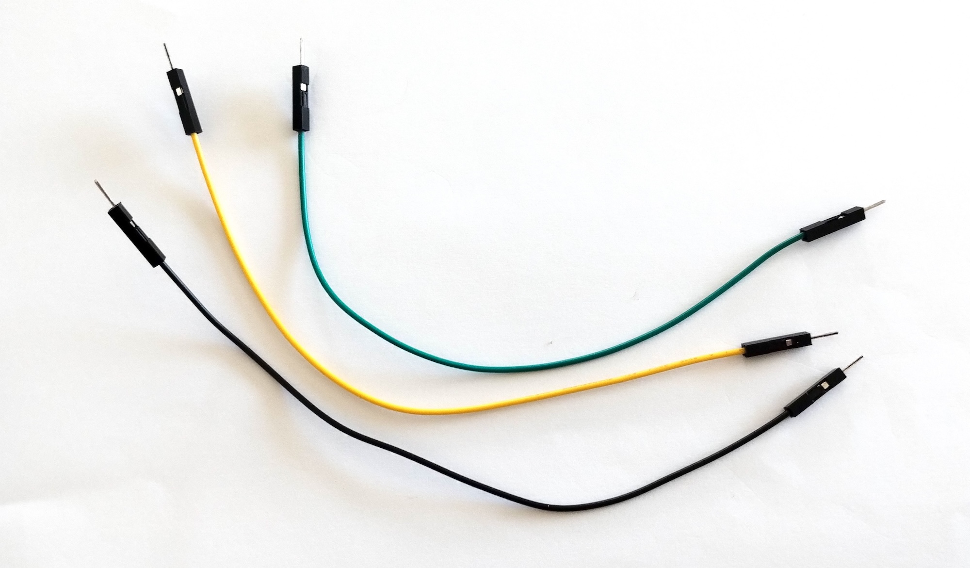
2.3. Jumper Wires
The serial adapter cable have female pin connectors. As Arduino boards also have female pin connectors, male-to-male jumper wires are used to connect the wires of the adapter cable to the board. In total, three male-to-male jumper wires are needed.
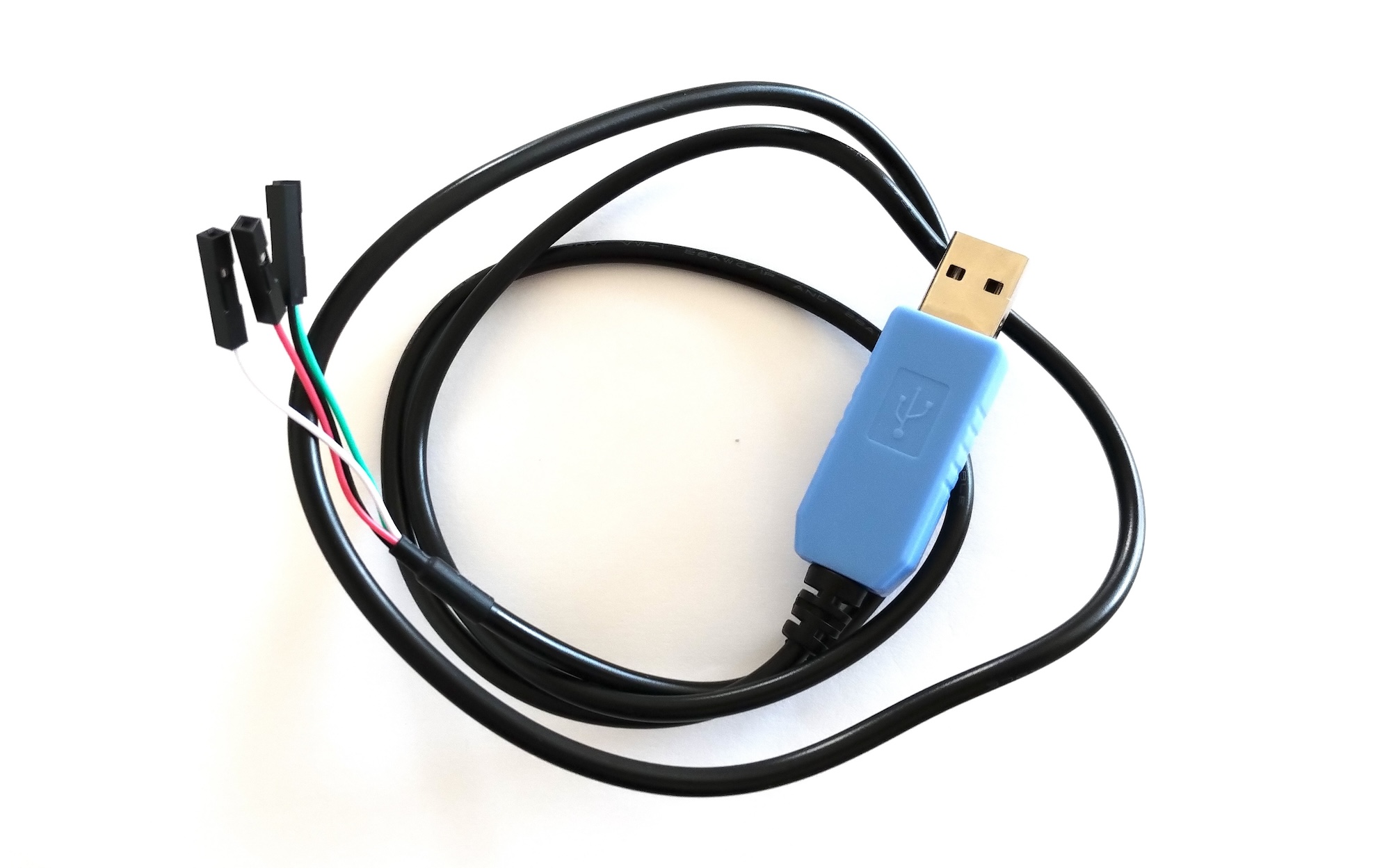
Serial adapter cable (without jumper wires attached):
Jumper wires:
Serial adapter cable with with jumper wires attached (yellow wire is attached to white):
Close-up of jumper wire connection (yellow wire attached to white):
3. Code Examples
3.1. Serial1
Serial1 is a predefined serial port that maps to pins 0 and 1:
pin0 - input  (RX) (green wire)
pin1 - output (TX) (white wire)
Code example:
#include <Arduino.h>

void setup()
{
  Serial1.begin(9600);
}

void loop()
{
  delay(1000);
  Serial1.println("HI WORLD");
}
3.2. SoftwareSerial
SoftwareSerial is a class that creates a mapping to custom pins numbers.
For exmaple, we can map pins 2 and 3 to input and output:
pin2 - input  (RX) (green wire)
pin3 - output (TX) (white wire)
Code example:
#include <Arduino.h>
#include <SoftwareSerial.h>

#define rxPin 2 // green
#define txPin 3 // white
SoftwareSerial dbgSerial(rxPin, txPin);

void setup()
{
  // Pin mode must be set
  pinMode(dbgRxPin, INPUT);
  pinMode(dbgTxPin, OUTPUT);
  dbgSerial.begin(9600);
}

void loop()
{
  delay(1000);
  dbgSerial.println("HI WORLD");
}
Do not forget to also connect the black wire to GND.
4. Pins for Arduino Uno R4 WiFi
One the Arduino Uno R4 WiFi, the following pins can be used for TX and RX.
4.1. TX (Output)
TX can be any digital pin, except D12 and D13, which conflicts with the build-in LED matrix.
4.2. RX (Input)
RX can be one of:
D0, D1, D2, D3, D6, D8, D11
4.3. References
Incorrect information re: SoftwareSerial RX pins
5. Serial Monitor
The Arduino IDE has a Serial Monitor that can be used to view the serial ouput from the device. There is also a command-line version available. There are also programs such as screen (macOS/Linux) and PuTTY (Windows) that can be used.
To view output from both the Application Firmware and the Core Firmwarecore, two serial sessions is needed. It is for example possible to use the Arduino IDE Serial Monitor in parallel with some other serial monitor software. One can also use two screen sessions on Linux/macOS.
5.1. Using PuTTY Windows
PuTTY is an example of a tool that can monitor serial port on Windows. For more information, see www.putty.org
5.2. Using Screen on Linux or macOS
First find the name of the port of the device.
Find the device on Linux:
lsusb
Find the device on macOS:
ls /dev/tty.*
The use the screen command to connect to the board.
For example, to connect to the board using 115200 baud, use this command:
screen /dev/cu.usbserial-14110 115200
Another baud rate can be specified on the command line. Here is an example of how to connect using 9600 baud:
screen /dev/tty.usbmodem142301 9600
Exit screen by pressing the following keys on the keyboard:
CTRL+A followed by K
5.3. Using the Arduino Command-Line Tools
The command-line tools provided by Arduino are very useful for monitoring serial output. The arduino-cli monitor command is used for this.
Command format for logging with timestamps:
arduino-cli monitor -c BAUD_RATE --timestamp -p PORT_NAME
Example:
arduino-cli monitor -c 115200 --timestamp -p /dev/tty.usbmodem11301
Command format to redirect log output to a file:
arduino-cli monitor -c BAUD_RATE --timestamp -p PORT_NAME > LOG_FILE
To view the output written to the log file during logging, the tail command can be used (Linux/macOS):
tail -f LOG_FILE
Terminate logging by pressing CTRL-C on the keyboard.
Instructions for how to install the Arduino command-line tools: arduino.github.io/arduino-cli/dev/installation/
Instructions for the monitor command: arduino.github.io/arduino-cli/dev/commands/arduino-cli_monitor/