Arduino Uno Enrollment Tutorial
1. Overview
This tutorial shows how to enroll an Arduino Uno with the RIoT Secure Platform. The modem used is an MKR WiFi 1010 mounted on a RIoT FUSION Shield. Once enrolled, the Arduino Uno can be monitored and updated over-the-air from the Management Console.
Notice: Some screenshots in this tutorial use example data and may differ from actual screens.
1.1. Enrollment Steps
Enrolling a device is done by registering it with the RIoT Secure Platform and installing the FUSION Core Firmware on the device.
The following are the steps in the process of enrolling a device:
- Prepare the device hardware. Assemble the device if needed, and make sure all cables needed are available.
- Create a device entry in the Management Console. Create a new device entry in the Management Console and configure it with the name and password of the network the device should connect to.
- Download RIoTInstaller Download the installer sketch RIoTInstaller.ino from the Management Console.
- Run RIoTInstaller.ino to install the core firmware on the device. Launch the RIoTInstaller.ino sketch in the Arduino IDE to install the FUSION Core Firmware on the modem of the device.
- Reboot the device. When RIoTInstaller.ino has finished writing the firmware to the device, reboot the device by pressing the reset button on MKR WiFi 1010. Once rebooted, the enrollment process will begin.
- Enrollment over-the-air. The device connects over the network to the OASIS Cloud to complete the firmware installation. This may take up to 5-10 minutes. The progress of the enrollment process can be inspected using the Serial Monitor in the Arduino IDE.
- Verify device status. When the Core Firmware has been successfully installed, the device is listed as “Enrolled” in the Management Console.
- Upload application firmware. The device is now ready to be updated with application firmware, which is uploaded over-the-air using the Management Console.
2. Prerequisites
2.1. Required Knowledge
To walk through this tutorial, familiarity with the RIoT Secure Platform, the Management Console and the appropriate tools to compile and export firmware is required.
Required knowledge:
- Familiarity with the RIoT Secure Platform
- How to use the Management Console
- How to setup and use the Arduino IDE
- How to create application firmware sketches in the Arduino IDE
- How to export firmware sketches from Arduino IDE
- Basic knowledge of the Core Firmware log
2.2. Required Components
The following items are needed:
- An Arduino Uno with a RIoT FUSION Shield and an MKR WiFi 1010 board (or a similar setup that includes the FUSION Shield)
- A microSD card formatted with FAT32
- An account for logging in to the Management Console
- A computer with the Arduino IDE installed
- USB cables to connect the two boards of the FUSION device to the computer.
- Information about the network connection that will be used for the FUSION device (WiFi name and password)
- An exported application firmware sketch in hex format. The exported firmware file will be deployed over-the-air to the device.
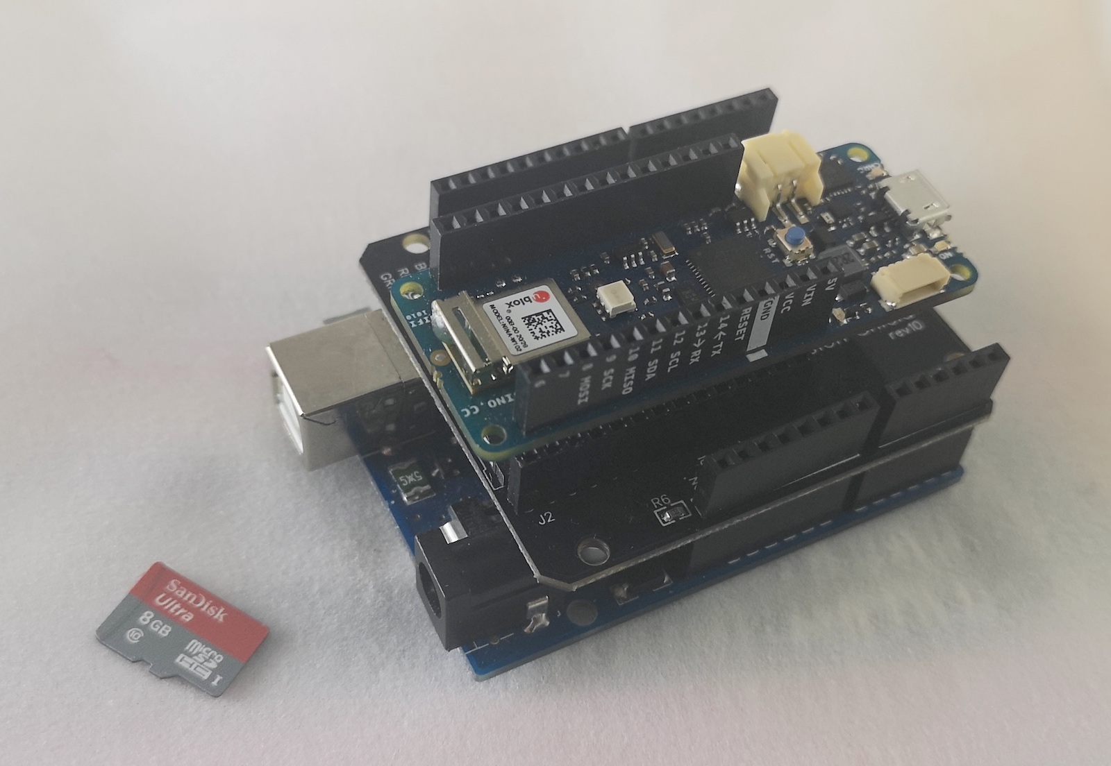
2.3. Assemble the FUSION Device
Assemble the Arduino Uno, RIoT Fusion Shield and MKR WiFi 1010 as shown in this photograph.
2.4. microSD Card Preparation
Important: The FUSION Device must be unplugged and powered OFF while inserting or removing the microSD card.
The FUSION device uses the microSD card as storage when downloading firmware over-the-air.
The file system on the microSD card should be clean FAT32 format. Ensure that the card is correctly formatted before proceeding with the tutorial.
2.4.1. Insert the microSD Card
Insert the microSD into the slot on the RIoT Fusion Shield (the middle board) as shown in the picture – ensure it goes all the way in.
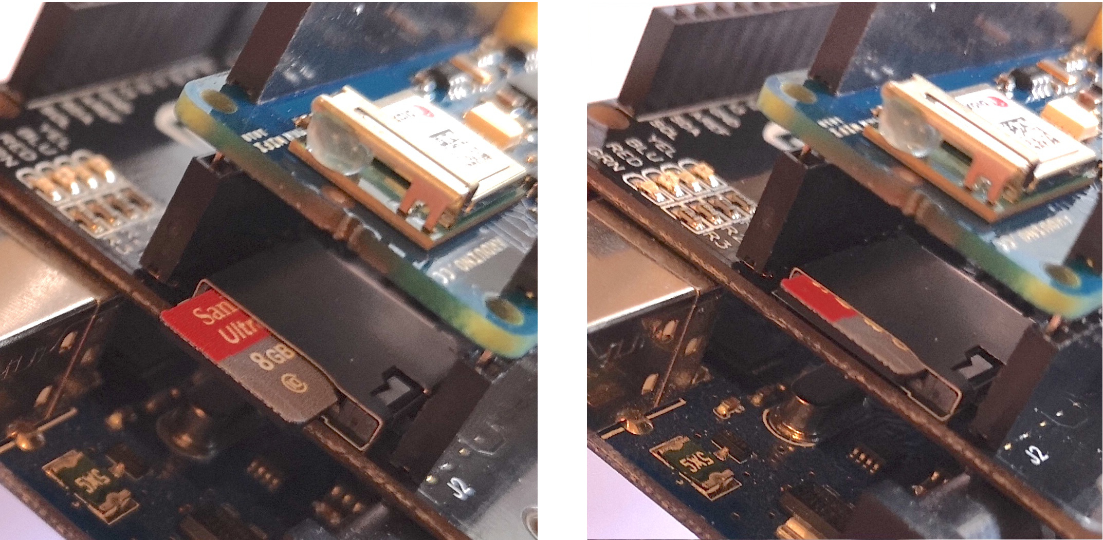
Important: The microSD card must remain inserted into the device once it has been installed. The microSD card is required for the FUSION Core Firmware to operate.
2.4.2. Formatting the SD Card
If the microSD card needs to be formatted, this can be done on a computer:
- On Windows, use the File Explorer to format the card. Select the SD card in the File Explorer, and choose the Format menu option.
- On macOS, use the Disk Utility program that comes with the system. From the Edit menu choose Erase and select FAT32 as the file system.
In the event problems occur, there are downloadable utilities on the Internet that can correctly format the microSD card, such as the “SD Memory Card Formatter” tool from the SD Association:
2.5. Prepare an Application Firmware Sketch
Application firmwares are created using the Arduino IDE. Firmware files are exported from the IDE in hex format and uploaded and deployed over-the-air using the Management Console.
The Export Compiled Binary menu command is used to export a sketch to hex format. For further details, see the Export Application Firmware reference guide.
For the purpose of this tutorial, it is suggested to create a basic blink sketch, that turns the onboard LED on and off.
If the sketch is named Blink.ino, the exported file for the Arduino Uno is named:
Blink.ino.hex
3. Create a Device Entry
Use the Management Console to create a new device entry for the device that will be enrolled with the RIoT Secure Platform.
3.1. Login to the Management Console
Login to the Management Console using a valid username and password.
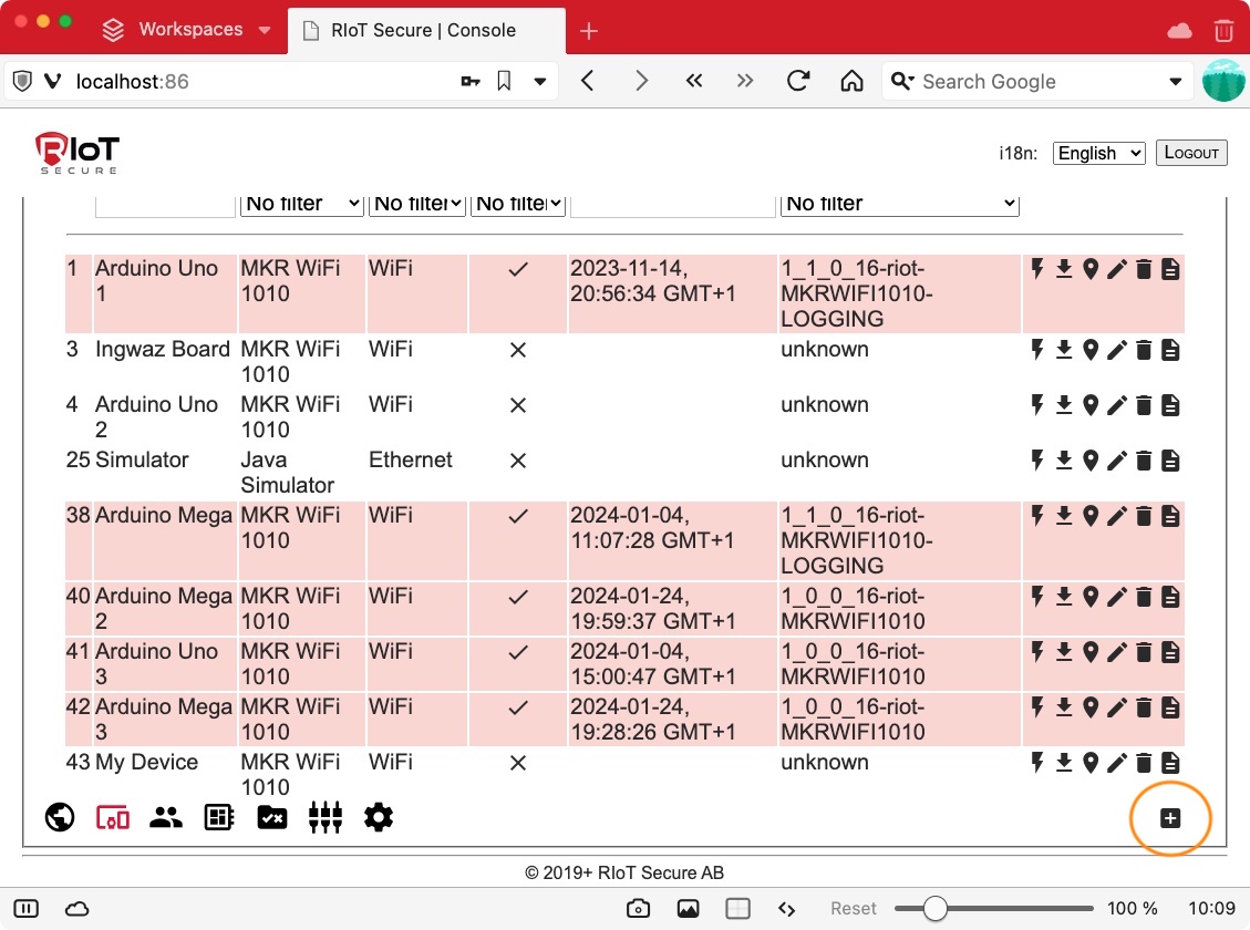
3.2. Add a New Device Entry
Navigate to the Devices Screen and click the “+” icon to add a new device:
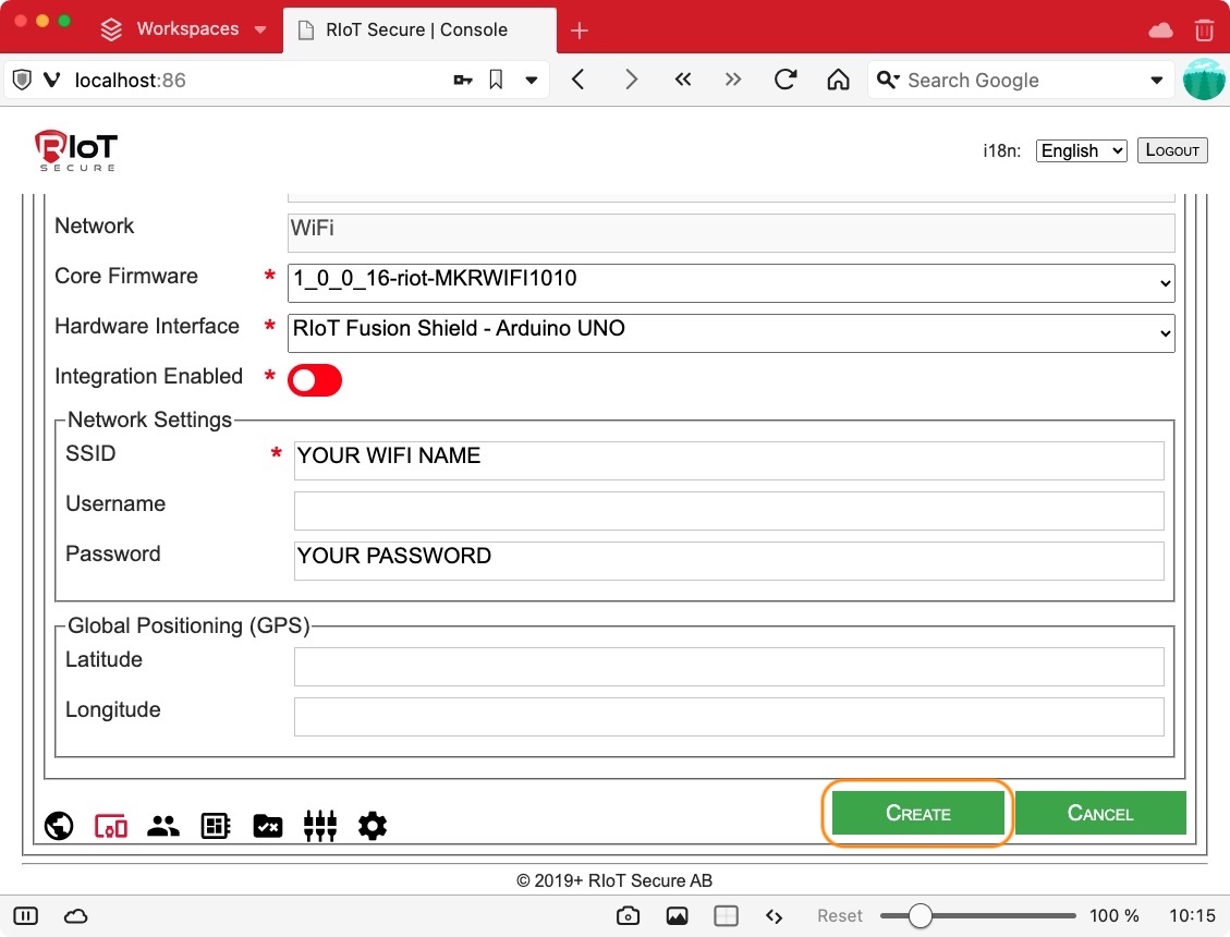
3.3. Fill in the Device Fields
Fill in the fields for the device, as illustrated by the screenshot. For a reference to the device fields, consult the Management Console Guide.
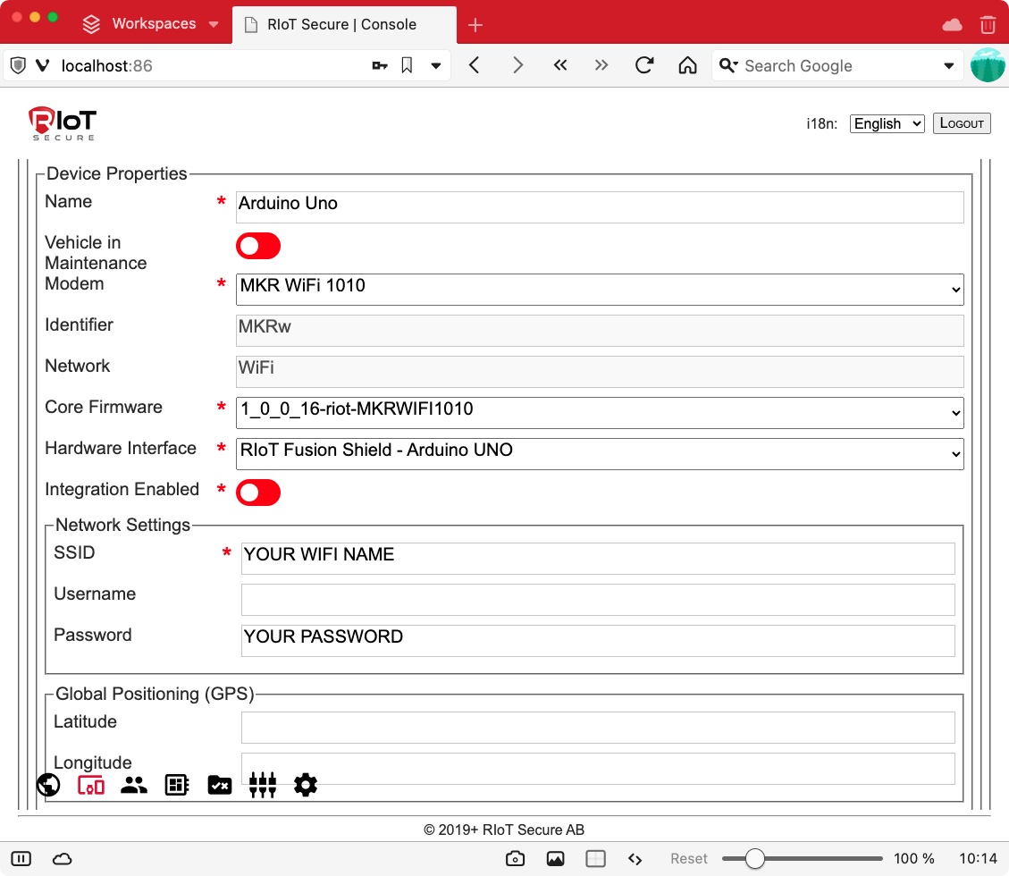
Optionally, a static GPS location can defined. Not all devices will have a GPS tracker; however, this does not mean that the device cannot be shown on the map.
Simply fill in the Latitude and Longitude fields to specify a static location. If at any point a GPS tracker is added to the board, the platform will automatically use the dynamic device location data.
3.4. Create the Device
When all required fields are filled in, create the device by clicking on the CREATE button at the bottom of the page.
The device is now shown in the list on the Devices Screen.
4. Download RIoTInstaller
RIoTInstaller is a sketch designed for the Arduino MKR device family that installs a secondary bootloader specifically designed for programming the SAMD21 microcontroller. The sketch then flashes the initial FUSION Core Firmware to the device.
Go to Devices Screen list view in the Management Console. Click the small “flash” icon to the right of the device entry. This will open a dialog box prompting to save a zip file that contains the installer sketch for the device.
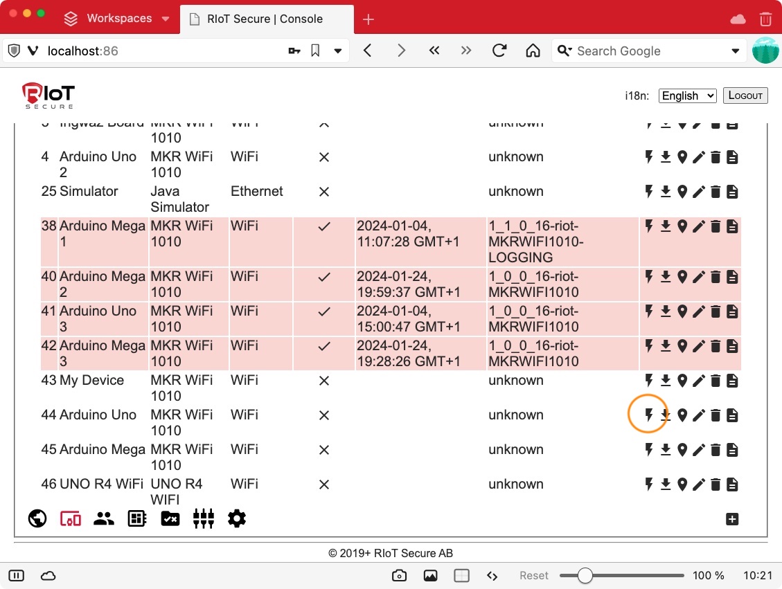
The downloaded zip file will be named:
RIoTInstaller_{device_id}.zip
For example, the installer zip file for the device with id 1 is named:
RIoTInstaller_1.zip
Unzipping this file will create a folder named RIoTInstaller_1. The following files should be present:
RIoTInstaller_1
  RIoTInstaller_1.ino
  (library files)
RIoTInstaller_1.ino is the Arduino sketch for the installer.
The next step is to open the RIoTInstaller ino sketch in the Arduino IDE and install it on the device.
5. Run RIoTInstaller
Follow the steps below to run the RIoTInstaller sketch. This will install the FUSION Core Firmware on the physical device.
5.1. Unzip the RIoTInstaller zip file
Unzip the downloaded RIoTInstaller zip file as explained in the previous step.
The name of the zip file contains the device id.
As an example, the zip file for the device with id 1 is named:
RIoTInstaller_1.zip
Expaning this file creates a folder with the installer sketch, which also contains the device id:
RIoTInstaller_1.ino
Double-check that the id of the sketch id is the desired device id - it will be permanently associated with the physical device.
To change the device id of a physical device, the RIoTInstaller sketch for the desired id must be downloaded and installed again.
5.2. Open the RIoTInstaller Sketch in the Arduino IDE
Open the RIoTInstaller ino file in the Arudino IDE by double-clicking it.
Next step is to connect the modem of the FUSION device to the computer using a USB cable and make the required settings in the Arduino IDE.
Configure Linux USB
On Linux systems, you need to add your user to the dialout group to grant full access to serial USB ports. Open a terminal and enter the following command:
sudo usermod -a -G dialout $USER
Then restart your computer to make changes take effect.
For further instructions, see the Linux USB Configuration guide.
5.3. Connect to the Modem over USB
Connect the MKR WiFi 1010 modem to the computer using a USB cable. Connecting the cable will provide upload of code from the Arduino IDE and power the modem.
Also power on the Arduino Uno by connecting a USB cable to the board.
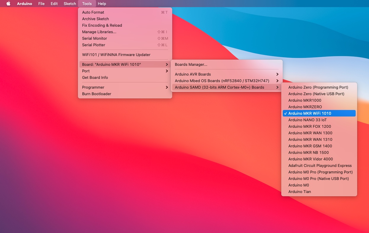
5.4. Select Board
In the Arduino IDE, open the Tools→Board menu, and select Arduino SAMD→Arduino MKR WiFi 1010.
5.5. Select Port
Select the port for the MKR WiFi 1010 board in the Tools→Port menu.
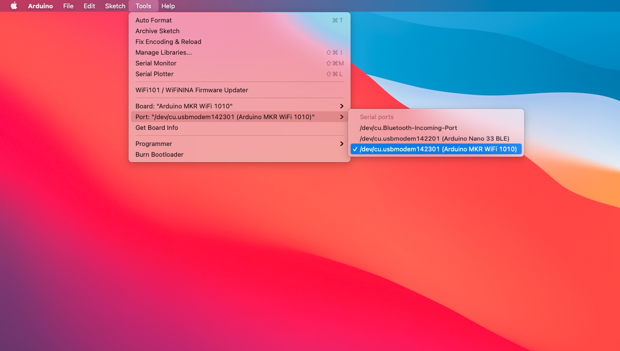
Good to Know: If the USB port of the MKR board cannot be found in the menu, try with double pressing the reset button on the MKR (quickly “click” the button twice). This places the device in “bootloader mode”, allowing the Arduino IDE to connect.
5.6. Upload RIoTInstaller to the Modem
Upload the RIoTInstaller sketch to the device by selecting the Sketch→Upload menu item, or by clicking the upload arrow button in the Arduino IDE.
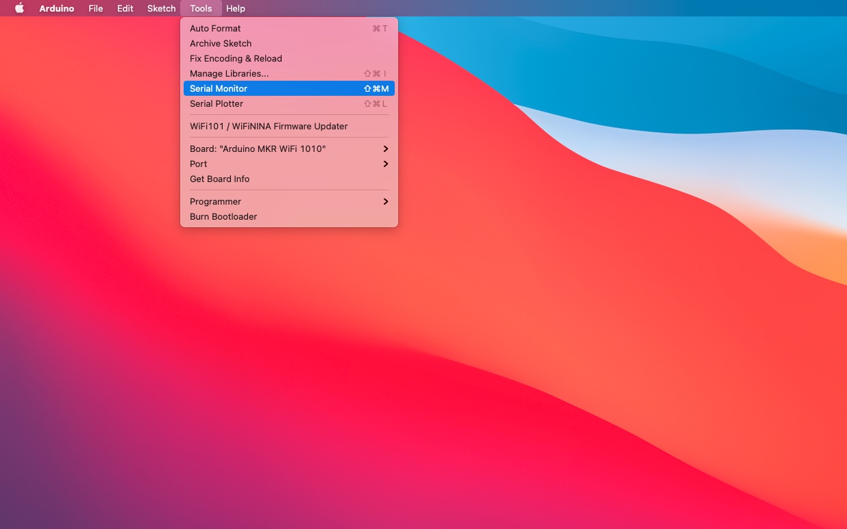
5.7. Open the Serial Monitor
Open the Serial Monitor window by selecting select the menu item Tools→Serial Monitor.
5.8. Select Baud Rate
Select baud rate 115200 in the Serial Monitor window (see screenshot below).
5.9. View RIoTInstaller Output
The output from RIoTInstaller should appear in the Serial Monitor. A text with instructions is displayed (the same text can be found in the source code of the RIoTInstaller.ino file).
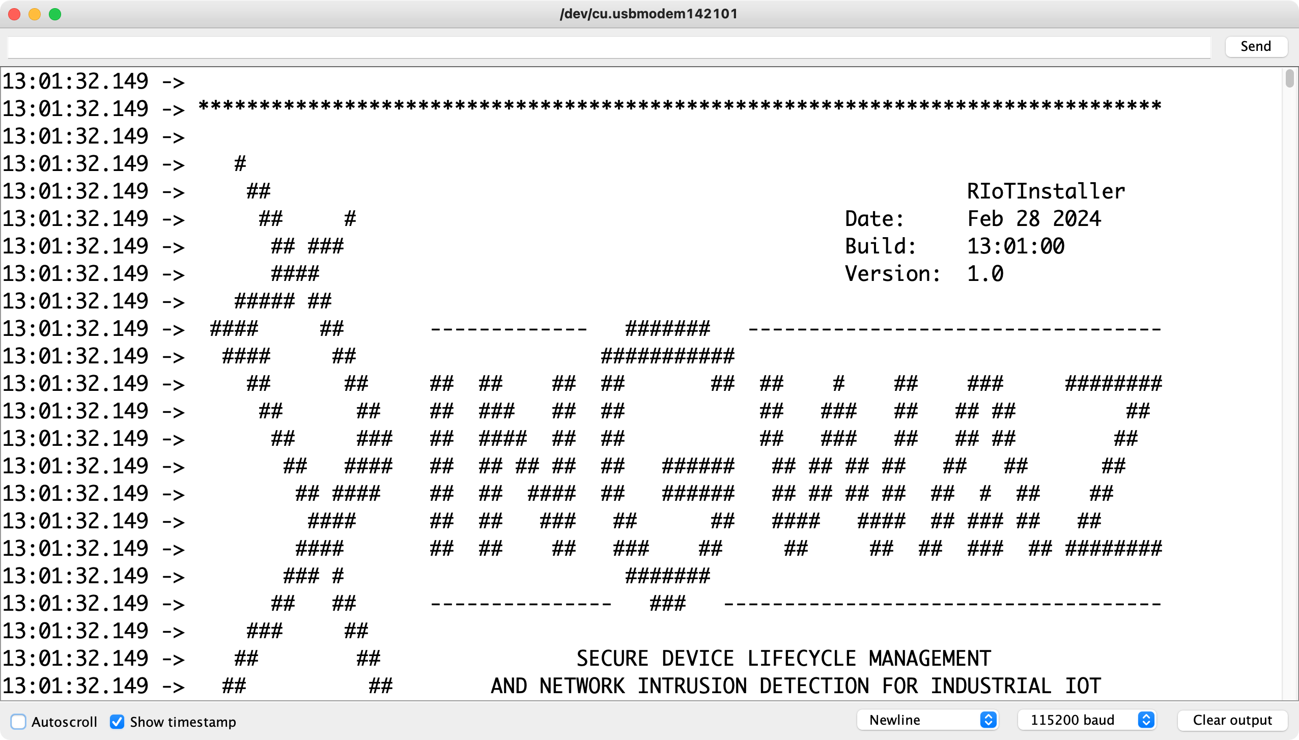
The device is now ready to be rebooted to complete the installation.
6. Restart the Device
Restarting the device will boot the FUSION Core Firmware, which will connect to the network to complete the enrollment of the device. This process may take up to 5-10 minutes.
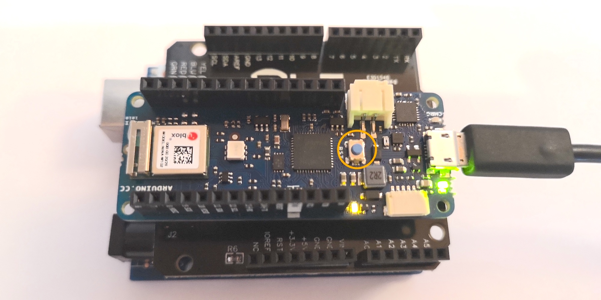
6.1. Press the Reset button on the Modem
Make sure that both the modem and the application board are be powered.
When ready, press and release (“click”) the reset button on the modem (the MKR WiFi 1010) to reboot the device. This will load the bootloader code installed by the RIoTInstaller sketch. The device will now connect to the OASIS Cloud to register the device with the server and update the firmware.
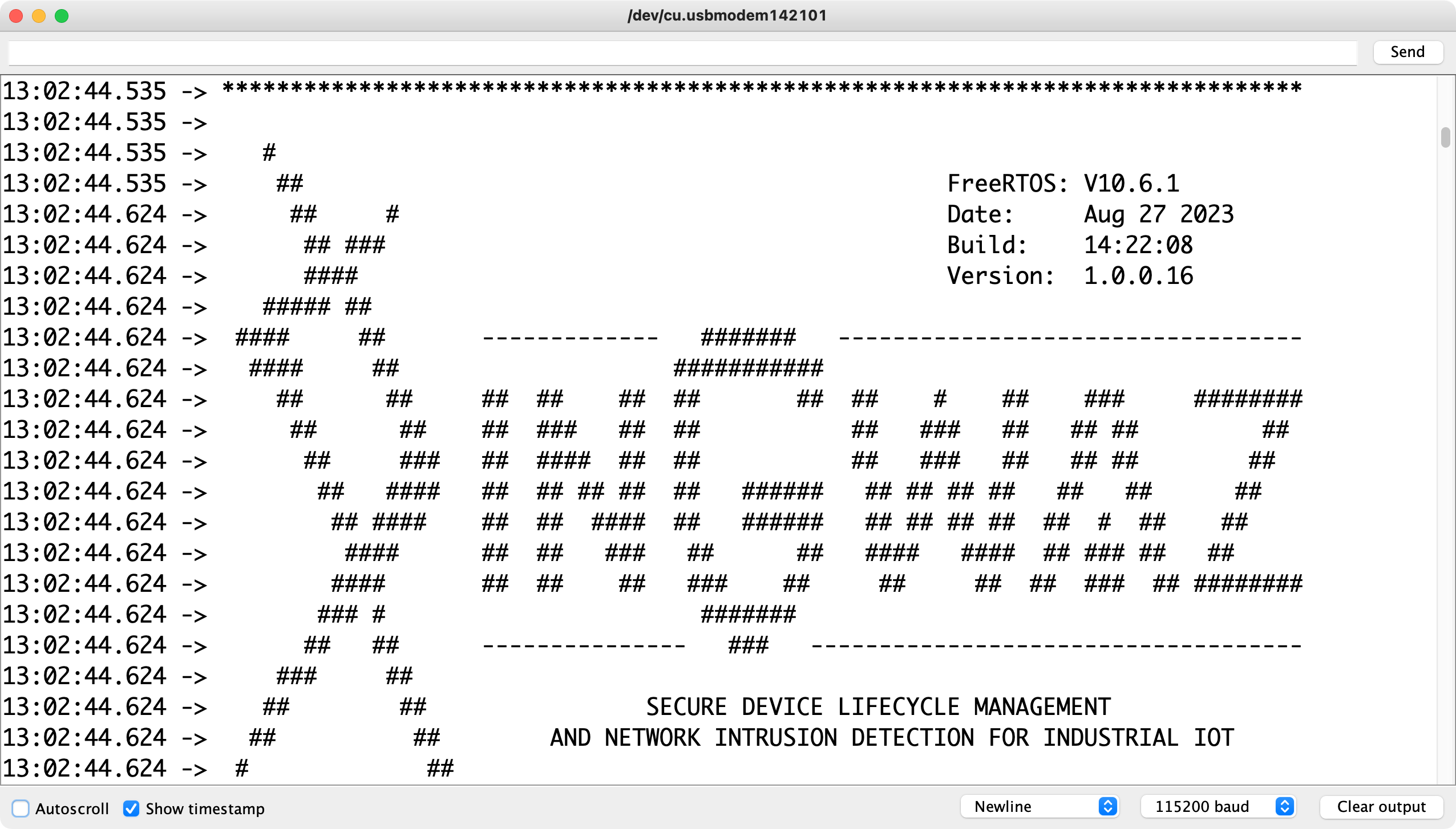
6.2. Inspect the Modem Log
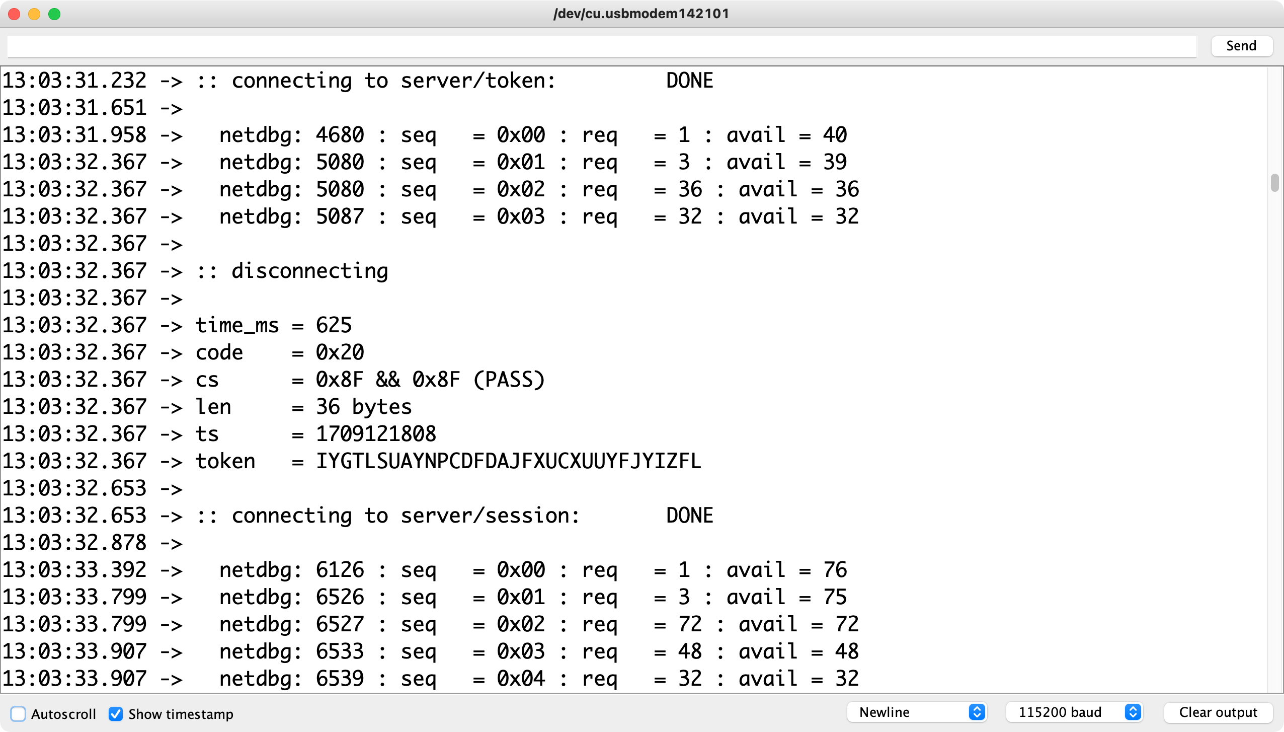
The output from the modem can be viewed in the Serial Monitor in the Arduino IDE. This is the output that is generated from the MKR WiFi 1010, the board on which the Core Firmware executes.
The modem log shows step-by-step information and the communication taking place with the IoT Server.
The log should be displayed in the Serial Monitor in the Arduino IDE.
To learn more about the information shown in the log, visit the Core Firmware Log documentation page.
7. Verify Device Status
To verify that the device is enrolled, check the device status in the Management Console.
Navigate to the Devices Screen in the Management Console and locate the device - the “Enrolled” field in the device listing should be checked.
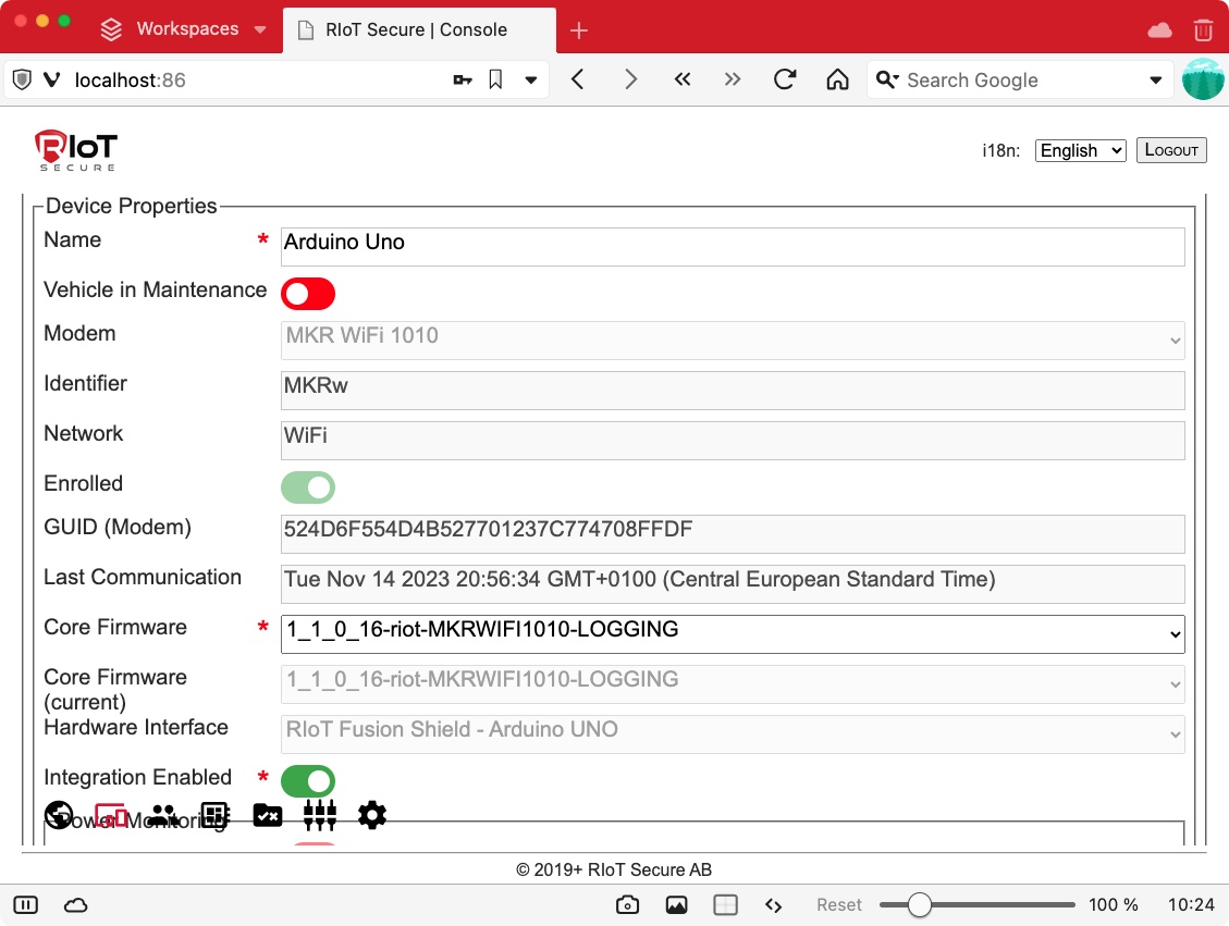
Click on the device to open the detailed device view.
The device should show the “Enrolled” switch with a green color (indicating a successful enrollment), as in the following screenshot.
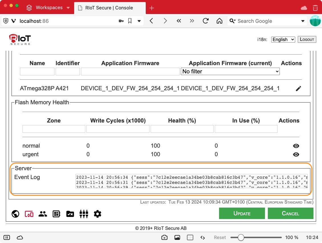
There should be data appearing in the Event Log at the bottom of the device view. Note that the topmost entry is the most recent log entry, with older entries following below. Here is an example of the event log:
The device has now been enrolled with the RIoT Secure Platform and will maintain a connection with the server as long as it is powered on.
If powered off, the device will reconnect when powered on again.
If the device should disconnect from the network, it will still operate and collect data, and reconnect when the network becomes available again.
The enrollment of the device is now complete.
8. Over-the-Air Firmware Updates
When the device has been enrolled, the application firmware can be updated over-the-air.
How to do this is detailed in the Firmware Over-the-Air Tutorial.