Device Communication Programming
1. Introduction
This document describes the device communication facilities available to embedded developers.
The RIoT Secure Platform features a secure, reliable, and easy-to-use networking architecture that allows for efficient data transfer between edge devices and a cloud application.
Related Documentation
Communication Authentication Reference - information about customer cloud server authentication methods.Packet Reference - detailed information about packet formats.
Device Communication Tutorial - hands-on guide for writing communication code.
2. Communication Architecture
This diagram shows the components involved in device-to-cloud communication:
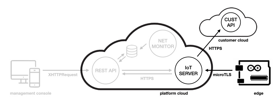
2.1. Edge Device
An edge device has two microcontrollers - the application microcontroller (running the application firmware) and the core microcontroller (modem running the core firmware).
The application firmware handles all application logic. The core firmware is responsible for network connectivity. These two components communicate internally over UART.
Data is sent to the server as packets. Packet data is encoded by the application in binary format. The application firmware transmits packet data to the core firmware, which sends it over the network to the IoT Server. The IoT Server then sends the data to the cloud server.
2.2. IoT Server
The IoT Server is a system component that routes packet data sent from edge devices to the corresponding cloud server.
The IoT Server converts binary packet data to JSON format, which is then sent to the cloud server.
2.3. Customer Cloud Server
2.3.1. Cloud Server Requests
The cloud server is the end point for data sent from edge devices. This server is set up and managed by the customer. Data is sent over HTTPS using a PUT request.
The body of the PUT request contains the packet data in JSON format, along with device identification and status information.
Data can be sent back to the device in the request response body, as string data (see the notes below and the tutorial for details).
The cloud server typically stores device data in a database, which can be accessed by cloud applications such a dashboards, data analysis tools, and monitoring tools.
Any server that can accept PUT requests can be used as cloud server. A common configuration is a web server with PHP and a database.
2.3.2. Destination URL
The URL that points to the cloud server is the Destination URL (also called Integration URL). This URL is specified in the Settings Screen of the Management Console.
The Destination URL is specified per tenant, and is shared by all devices of a tenant.
Thus, there is one cloud server end point per tenant. Multiple applications can be hosted on a single server end point by routing incoming data using the packet information.
2.4. Cloud Applications
Typically, an IoT system has one or more cloud applications that are used to monitor and manage devices and device data.
Web applications are commonly used for this purpose. Mobile apps (native or web-apps) are also a popular solution.
Cloud applications can interact with the RIoT Secure Platform in two ways:
Customer Cloud Server: Data stored on the cloud server can be accessed using common web technologies such as PHP or JavaScript.
REST API: The RIoT Secure REST API can be used to access device data and manage devices. With the REST API, advanced functionality, such as device firmware over-the-air updates, are available.
The above two data sources are distinctly different and compliment each other.
The cloud server is used for storing device application data, such as sensor data. This data is handled by the customer cloud server, and is not stored on the RIoT Secure Platform.
The REST API is used to access and manage device system data stored on the RIoT Secure Platform. The RIot Secure Management Console is an example of an application that uses the REST API.
Customers can develop custom dashboards and management consoles, and even access the Customer Cloud and the REST API from the same application, if desired.
3. Sending Data (Edge Device)
This section outlines how data packets are created and sent from the edge device.
3.1. Packet Data
Data is sent to the server as packets of data. Each packet has one or more components. Each components represent a value, such as an integer.
Packet data is in binary format. This ensures best performance on embedded devices.
There are library functions available to embedded application developers for encoding and sending packet data.
3.2. Packet Definitions
Packet formats are defined in the Management Console UI (or via the REST API).
The packet data format is described in the Packet Reference documentation.
3.3. Creating and Queueing Packets
When sending a packet, the application first creates a packet data buffer in binary format. This buffer contains the packet priority level, the identifier, the length of the packet data, and the actual data. When the packet buffer has been created, it is queued for delivery.
An edge device has two microcontrollers (Application and Core). When the application firmware requests a packet to be queued, the packet data is transmitted over UART to the microcontroller running the core firmware, which performs the network requests.
This separation of concerns simplifies application development and ensures a high level of security, reducing the risk for application specific errors compromising network security and reliability.
Packets are sent to the IoT server over uTLS, a secure binary messaging protocol.
3.4. Packet Priority
When creating data packets, the application developer sets a priority level for each packet. There are two priority levels: normal and high (“urgent”).
-
High Priority: Packets with high priority are sent as soon as they are queued.
-
Normal Priority: Packets with normal priority are sent on the next scheduled connection event (typically once a minute).
3.5. Connection Interval
The Core Firmware connects to the IoT Server on regular intervals, typically every 60 seconds (the connection interval is a system setting defined by the system administrator).
On each connection, queued packets with normal priority are sent to the server.
Packets with high (“urgent”) priority are sent as soon as they are queued.
3.6. Buffering Packets
Buffering ensures that no packets are lost.
Packets with normal priority level that are queued for sending are buffered by the Core Firmware until the next connection event.
If network connectivity is not avaliable, packets are buffered until the network is available again.
4. Receiving Data (Edge Device)
The application firmware on the edge device can receive incoming data.
There are two types of incoming data:
- system data sent by the core firmware (e.g. location data)
- data sent from the cloud server.
4.1. Incoming System Data
Incoming data is system defined data packets, such as GPS data and system messages.
4.1.1. GPS Data
Location data is sent to the application when a GPS module is installed on the edge device. This enables the application firmware to implement functionality such as geofencing.
4.1.2. System Data
System data includes events such as Ignition On and Off. This is sent to the application when the corresponding hardware is installed on the device.
4.2. Incoming Cloud Server Data
The customer cloud server can (optionally) send data back to the edge device in the response body of the PUT request.
The data returned to the device is specified as a string. The HTTP response body returned from the cloud server should contain a JSON object with the key “Message” and the string value. For example:
{ "Message": "YOUR STRING DATA" }
String data received by the application firmware is in a buffer that holds a sequence of characters with a defined length (see the Device Communication Tutorial for an example).
5. Application Firmware Program Structure (C++)
This section describes the program structure of an application firmware that communicates over the network.
5.1. Library Functions
File riotuart.h provides library functions for sending and receiving data.
Applications should include riotuart.h in the beginning of the program.
An instance of class RIoTUART is created in variable riotUART when riotuart.h is included. This class provides functions for managing communication.
Click to view riotuart.h
//--------------------------------------------------------------------------
// @riotuart.h
//
// (c) RIoT Secure AB
//--------------------------------------------------------------------------

//--------------------------------------------------------------------------
// DEVELOPER WARNING
//
// do not modify the source code in any way - it is coded specifically to
// interface with the RIoTClient for the exchange of messages to and from
// the microcontroller, local modem level services and internet services.
//
// RIoTUART communication is restricted to send up to 255 bytes of data
// at a time (len is defined as a uint8_t within the communication protocol)
// the communication protocol is as follows, the code provided implements
// the receival and sending of data over a UART confirming to the protocol.
//
//   0x02 LEN { DATA } CS 0x03
//
//--------------------------------------------------------------------------

#ifndef RIOTUART_H
#define RIOTUART_H

#if   !defined(RIOT_UART_NATIVE) && !defined(RIOT_UART_SOFTWARE)
#error "RIoTUART - must define either RIOT_SERIAL_NATIVE or RIOT_SERIAL_SERIAL"
#elif  defined(RIOT_UART_NATIVE) && defined(RIOT_UART_SOFTWARE)
#error "RIoTUART - cannot define both RIOT_SERIAL_NATIVE or RIOT_SERIAL_SOFTWARE together"
#endif

#define CORE_SER_MAX_DATA_LEN 256
#define CORE_SER_RX_BUF_SIZE  (CORE_SER_MAX_DATA_LEN + 2)  //          { DATA } CS 0x03 - 2 extra bytes
#define CORE_SER_TX_BUF_SIZE  (CORE_SER_MAX_DATA_LEN + 4)  // 0x02 LEN { DATA } CS 0x03 - 4 extra bytes

//--------------------------------------------------------------------------
// globals
//--------------------------------------------------------------------------

int8_t  g_application_status;

#define APP_STATE_IDLE               0
#define APP_STATE_INIT               1
#define APP_STATE_LOOP               2
#define APP_STATE_QUIT               3

// SerialX is using the standard Serial UART
#ifdef RIOT_UART_NATIVE
#define SerialX Serial
#endif

// SerialX is using a SoftwareSerial UART using custom pins
#ifdef RIOT_UART_SOFTWARE
#define serialXRxPin MOSI
#define serialXTxPin MISO
SoftwareSerial SerialX(serialXRxPin, serialXTxPin);
#endif

typedef void (*RIoTUARTCallback)(uint8_t *buf, size_t len);

class RIoTUART
{
  public:
    void     begin(RIoTUARTCallback callback);
    void     loop();
    bool     queue(uint8_t *buf, size_t ofs, size_t len);
    void     end();

  private:

    // our receive buffer
    bool     rx_start;
    uint8_t  rx_buf[CORE_SER_RX_BUF_SIZE];
    size_t   rx_buf_idx;
    size_t   rx_len;
    uint8_t  rx_cs;

    // our transmit buffer
    uint8_t  tx_buf[CORE_SER_TX_BUF_SIZE];
    size_t   tx_buf_idx;
    size_t   tx_len;
    uint8_t  tx_cs;

    RIoTUARTCallback callback;
};

// there should only be one instance of RIoTUART defined
RIoTUART riotUART;

//--------------------------------------------------------------------------
// implementation
//--------------------------------------------------------------------------

// void
// RIoTUART::begin(RIoTUARTCallback callback)
//
// initialize the connection between the RIoTClient and the application.
// this should be placed in the setup() function of the main sketch
//
// @param callback: function pointer - executed on receival of a data packet
// @return none

void
RIoTUART::begin(RIoTUARTCallback callback)
{
  // initialize the serial connection to RIoT Fusion
#ifdef RIOT_UART_SOFTWARE
  pinMode(serialXRxPin, INPUT);
  pinMode(serialXTxPin, OUTPUT);
#endif
  SerialX.begin(57600);

  // initialize buffers
  memset(this->rx_buf, 0, CORE_SER_RX_BUF_SIZE);
  this->rx_start   = false;
  this->rx_buf_idx = 0;
  this->rx_len     = 0x100; // impossible value

  // initialize buffers - for sending data
  memset(this->tx_buf, 0, CORE_SER_TX_BUF_SIZE);
  this->tx_buf_idx = 2;
  this->tx_buf[0]  = 0x02; // STX
  this->tx_buf[1]  = 0x00; // len (to be provided later)

  // register the callback when data is received
  this->callback = callback;
}

// void
// RIoTUART::loop()
//
// maintain connection with RIoTUART, recieve and send messages from
// to allow communication betwenthe RIoTClient and the application.
// this should be placed in the loop() function of the main sketch
// user derived code in should not block code execution; or the UART
// connection may not be maintained and will prevent exchange of data
//
// @param  none
// @return none

void
RIoTUART::loop()
{
  //
  // RECEIVING - attempt to receive a whole message if possible
  //

  // does any data exist on the serial UART?
  while (SerialX.available())
  {
    // read the character from the UART
    uint8_t c = (uint8_t)SerialX.read();
    switch (c)
    {
      // STX
      case 0x02:
           // if no packet defined yet - great, we may have one
           if (!this->rx_start && (this->rx_len == 0x100))
           {
             this->rx_buf_idx = 0;
             this->rx_start   = true;  // ok; we now have a packet
           }

           // if the packet is started, the 0x02 is part of the packet
           else
           {
             // store the 0x02 in the receive buffer
             goto riotuart_loop_store;
           }
           break;

      // ETX
      case 0x03:
           // packet hasn't started - ignore data until STX received
           if (this->rx_len != 0x100)
           {
             // if the packet is started, the 0x03 may be part of the packet
             if (this->rx_buf_idx < (this->rx_len+1))
             {
               // store the 0x03 in the receive buffer
               goto riotuart_loop_store;
             }
             else

             // if we have received all data - the end of the message
             {
               // calculate the checksum (excluding CS itself)
               this->rx_cs = 0;
               for (size_t i=0; i<this->rx_len; i++)
                 this->rx_cs ^= this->rx_buf[i];

               // does the checksum match (ensure type == same)
               if (this->rx_cs == this->rx_buf[this->rx_len])
               {
#if defined(ENABLE_DEBUG)
                 // debugging purposes
                 dbgUART.println(":: recv");
                 dbgUART.print("length:     ");
                 dbgUART.println(this->rx_len);
                 dbgUART.print("checksum:   0x");
                 c = this->rx_cs;
                 if (c < 16) dbgUART.write('0');
                 dbgUART.println(c, HEX);
                 dbgUART.print("recv (HEX): ");
                 for (size_t i=0;i<this->rx_len; i++)
                 {
                   c = this->rx_buf[i];
                   if (c < 16) dbgUART.write('0');
                   dbgUART.print(c, HEX);
                   if (i != (this->rx_len-1)) dbgUART.write(' ');
                 }
                 dbgUART.println();
                 dbgUART.print("recv (ASC): ");
                 for (size_t i=0; i<this->rx_len; i++)
                 {
                   c  = this->rx_buf[i];
                   if ((c >= 0x20) && (c < 0x7f)) dbgUART.write(c);
                   else                           dbgUART.write('.');
                 }
                 dbgUART.println();
                 dbgUART.flush();
#endif

                 //
                 // MICROCONTROLLER CONTROL
                 //

                 // START
                 if (strncmp((char *)this->rx_buf, "START", 5) == 0)
                 {
                   g_application_status = APP_STATE_INIT;
                 }
                 else

                 // FINISH
                 if (strncmp((char *)this->rx_buf, "FINISH", 6) == 0)
                 {
                   g_application_status = APP_STATE_QUIT;
                 }
                 else

                 //
                 // OTHER MESSAGES - WHILE RUNNING
                 //

                 // we only process messages if the application is running
                 if (g_application_status == APP_STATE_LOOP)
                 {
                   this->callback(this->rx_buf, this->rx_len);
                 }
                 else

                 // not started and receiving messages already - initialize
                 {
                   g_application_status = APP_STATE_INIT;
                 }

                 // prepare for a new message to be received
                 this->rx_start   = false;
                 memset(this->rx_buf, 0, CORE_SER_RX_BUF_SIZE);
                 this->rx_buf_idx = 0;
                 this->rx_len     = 0x100; // impossible value
               }
               else
               {
#if defined(ENABLE_DEBUG)
                 dbgUART.println(":: RIoTUART.recv - message checksum mismatch");
#endif
               }
             }
           }

           // we are done; move along to next message
           goto riotuart_loop_recv_done;

      default:

riotuart_loop_store:;

           // start of packet? first byte is length
           if (this->rx_start)
           {
             this->rx_start = false;
             this->rx_len   = c;
           }
           else

           // packet hasn't started - ignore data
           if (this->rx_len != 0x100)
           {
             // store the value
             this->rx_buf[this->rx_buf_idx++] = c;

             // have we received too many bytes? malformed packet or bogus?
             if (this->rx_buf_idx > (this->rx_len+2))
             {
#if defined(ENABLE_DEBUG)
               // debugging purposes
               dbgUART.println(":: RIoTUART.recv - rx buffer overflow");
#endif

               // prepare for a new message to be received
               this->rx_start   = false;
               memset(this->rx_buf, 0, CORE_SER_RX_BUF_SIZE);
               this->rx_buf_idx = 0;
               this->rx_len     = 0x100; // impossible value

               // we are done; move along to next message
               goto riotuart_loop_recv_done;
             }
           }
           break;
    }
  }

riotuart_loop_recv_done:;

  //
  // SENDING - if the developer has queued up any messages, send them
  //

  // do we have anything to send?
  if ((this->tx_buf_idx > 2) && (this->tx_buf_idx < 257))
  {
    // we now know the length of our packet
    this->tx_len    = this->tx_buf_idx-2;
    this->tx_buf[1] = this->tx_len;

    // calculate the checksum of the entire message
    this->tx_cs = 0;
    for (size_t i=0; i<this->tx_len; i++)
      this->tx_cs ^= this->tx_buf[i+2];

    // and now we know the checksum
    this->tx_buf[this->tx_len+2] = this->tx_cs;
    this->tx_buf[this->tx_len+3] = 0x03; // ETX

#if defined(ENABLE_DEBUG)
    uint8_t c;

    dbgUART.println(F(":: send"));
    dbgUART.print(F("length:     "));
    dbgUART.println(this->tx_len);
    dbgUART.print(F("checksum:   0x"));
    c = this->tx_cs;
    if (c < 16) dbgUART.print(F("0"));
    dbgUART.println(c, HEX);
    dbgUART.print(F("send (HEX): "));
    for (size_t i=0;i<this->tx_len; i++)
    {
      c = this->tx_buf[i+2];
      if (c < 16) dbgUART.write('0');
      dbgUART.print(c, HEX);
      if (i != (this->tx_len-1)) dbgUART.write(' ');
    }
    dbgUART.println();
    dbgUART.print(F("send (ASC): "));
    for (size_t i=0; i<this->tx_len; i++)
    {
      c = this->tx_buf[i+2];
      if ((c >= 0x20) && (c < 0x7f)) dbgUART.write(c);
      else                           dbgUART.write('.');
    }
    dbgUART.println();
#endif

    // 0x02 LEN { DATA } CS 0x03
    SerialX.write(this->tx_buf, this->tx_len+4);
    SerialX.flush();

    // initialize buffers - for sending data
    memset(this->tx_buf, 0, CORE_SER_TX_BUF_SIZE);
    this->tx_buf_idx = 2;
    this->tx_buf[0]  = 0x02; // STX
    this->tx_buf[1]  = 0x00; // len (to be provided later)
  }
}

// void
// RIoTUART::queue(uint8_t *buf, size_t ofs, size_t len)
//
// queue a message into the RIoTUART that will be sent during the
// subequence maintenance handler of the RIoTUART connection.
//
// @param  buf - a pointer to the buffer to send
// @param  ofs - the offet within the buffer to retrieve bytes
// @param  len - the number of bytes to queue
// @return true on success, false if buffer is full
//
// EXAMPLE USAGE:
//
// {
//   if (riotUART.queue(rx, len)) // success
//   else { }                     // failure, buffer full
// }

bool
RIoTUART::queue(uint8_t *buf, size_t ofs, size_t len)
{
  bool success = false;

  // do we have room for the message in the tx buffer?
  if ((this->tx_buf_idx + len) < (CORE_SER_TX_BUF_SIZE-4))
  {
    // insert the message into the queue
    memcpy(&this->tx_buf[this->tx_buf_idx], &buf[ofs], len);
    this->tx_buf_idx += len;

    // inform the developer the message was queued successfully
    success = true;
  }

  return success;
}

// void
// RIoTUART::end()
//
// terminate the connection between the RIoTClient and the application.
//
// @param  none
// @return none

void
RIoTUART::end()
{
  // terminate the serial connection to RIoT Fusion
  SerialX.end();
#ifdef RIOT_UART_SOFTWARE
  pinMode(serialXRxPin, INPUT);
  pinMode(serialXTxPin, INPUT);
#endif
}

#endif

//--------------------------------------------------------------------------
5.1.1. Initialization
Call the begin function to set a receive data callback function and initialize the connection between the core fimware and the application.
// void RIoTUART::begin(RIoTUARTCallback callback)
// @param callback: function pointer - executed on receival
// of a data packet
// @return none
Example usage:
riotUART.begin(application_riotuart_callback);
5.1.2. Processing
Call the loop function to process communication to recieve and send messages. Application code shold not block code execution. Use a timer in place of calls to delay (see the Device Communication Tutorial for example code).
// void  RIoTUART::loop()
// @param  none
// @return none
Example usage:
riotUART.loop();
5.1.3. Termination
Call the end function to terminate communication.
// void RIoTUART::end()
// @param  none
// @return none
Example usage:
riotUART.end();
5.1.4. Sending Data
Packet data is queued for sending by calling the queue function:
// void RIoTUART::queue(uint8_t *buf, size_t ofs, size_t len)
// @param  buf - a pointer to the buffer to send
// @param  ofs - the offet within the buffer to retrieve bytes
// @param  len - the number of bytes to queue
// @return true on success, false if buffer is full
Example usage:
riotUART.queue(packet, 0, PACKET_SIZE);
5.1.5. Receiving Data
Data is recieved in a callback function of type RIoTUARTCallback:
// callback function type
// typedef void (*RIoTUARTCallback)(uint8_t *buf, size_t len);
// @param  buf - a pointer to buffer with incoming data
// @param  len - the number of bytes to receive
// @return none
See below for a code example that shows how to use the receive callback function.
5.1.6. Application State
File riotuart.h declares the following variable which holds the application state:
int8_t g_application_status;
See below for a code example that shows how to manage application state.
5.1.6. Application State Constants
File riotuart.h defines the following constants for tracking the application state:
#define APP_STATE_IDLE 0
#define APP_STATE_INIT 1
#define APP_STATE_LOOP 2
#define APP_STATE_QUIT 3
See below for a code example that shows how to manage application state.
5.2. Program Structure
The following skeleton code shows how to structure application firmware code that uses the communication functions to send and recieve data.
#include <Arduino.h>
#include <SoftwareSerial.h>
#include <stdint.h>
#include <stdlib.h>

// Include riotuart library
#include "riotuart.h"

#define GPS_MESSAGE_PACKET_SIZE 19 // size of predefined GPS packet

// Application init function
void application_init()
{
  // perform initalization
}

// Application loop function
void application_loop()
{
  // perform application logic
  // read sensors, send data to the cloud etc.
  // application code shold not block code execution
  // a timer should be used to queue data on regular intervals
}

// Application callback that processes incoming messages
void application_riotuart_callback(uint8_t *rx, size_t len)
{
  if (rx[0] == '#') // # means incoming data packet
  {
    // check if valid GPS packet and handle data
    if (('+' == rx[1]) && (len == GPS_MESSAGE_PACKET_SIZE))
    {
      // process GPS data (optional)
    }
  }
  else
  {
    // process incoming string data from the customer cloud server
    // string data is in buffer pointed to by rx param
    // number of characters is in len param
  }
}

// Application shutdown function
void application_quit()
{
  // handle shutdown as needed
}

// Arduino setup function
void setup()
{
  riotUART.begin(application_riotuart_callback);
  delay(500);
  g_application_status = APP_STATE_IDLE;
}

// Arduino loop function
void loop()
{
  riotUART.loop();

  if (g_application_status != APP_STATE_IDLE)
  {
    switch (g_application_status)
    {
      case APP_STATE_INIT:
        application_init();
        g_application_status = APP_STATE_LOOP;
        break;

      case APP_STATE_LOOP:
        application_loop();
        break;

      case APP_STATE_QUIT:
        application_quit();
        g_application_status = APP_STATE_IDLE;
        break;
    }
  }
}
The companion Device Communication Tutorial contains a code example that shows how to use the above library functions.
6. Packet Data Format
Packet data formats are defined in the Packet Editor (or via the REST API).
The packet data format is detailed in the Packet Reference documentation.
7. Cloud Server Data Format (JSON)
The IoT Server receives binary data from the edge device, which is converted to JSON data according to the packet definition, and sent to the customer cloud server pointed to by the tenant Destination URL.
The JSON data is sent to the customer cloud server in the body of an HTTP PUT request.
7.1. JSON Data Format
Data sent to the customer cloud server is in JSON object format (see example below):
{
  ...
}
The following is the definition of each field in the data object.
7.1.1. Data Object
The JSON object sent to the server has the following fields:
| Field | Description |
|---|---|
| guid | device identifier |
| sess | session identifier |
| v_core | core firmware version |
| microcontroller | array of microcontroller objects |
| ign | ingnition status (used for vehicles) |
| modem_info | object with information about the modem device |
| memory | array of device memory status objects |
| hardware | object with hardware capabilities |
| packets | array of data packet objects (may be empty) |
7.1.2. Microcontroller Object
The microcontroller array contains objects in the following format:
| Field | Description |
|---|---|
| v_appl | application firmware version |
| identifier | microcontroller identifier |
An edge device can have from 1 to 4 application microcontrollers.
7.1.3. Modem Info Object
The modem_info object contains properties such as the MAC address of the device.
The fields of this object are specific to the type of modem used.
7.1.4. Memory Info Object
The memory array contains objects in the following format:
| Field | Description |
|---|---|
| zone | type of memory; "normal" or "urgent" |
| cycles | number of cycles |
| health | memory health (0 - 100) |
| inuse | use status |
An edge device have two memory zones, “normal” and “urgent”.
7.1.5. Hadware Info Object
The hardware object has the follwing fields indicating hardware capabilities:
| Field | Description |
|---|---|
| MEM | boolean represent by 0 or 1 |
| SD | boolean represent by 0 or 1 |
| gps | boolean represent by 0 or 1 |
7.1.6. Packet Object
The packet array contains objects in the following format:
| Field | Description |
|---|---|
| ts | timestamp |
| PACKET_NAME | subobject that contains packet component values; this key for this field is the packet name |
There may be multiple keys (packet subobjects) in a packet object. Each packet subobject contains the component value(s) for the specific packet with the name given by the key.
Components values have the following format:
| Field | Description |
|---|---|
| COMPONENT_NAME | the value of the component |
When a packet has multiple component, there are multiple keys in the packet subobject. Each component key is identified by the component name.
The packet array may be empty when there are no packets sent in the exchange from the edge device.
Example packet array with one packet (CounterPacket) that has a single component (Counter):
"packets": [
  {
    "ts": 1699998738250,
    "CounterPacket": {
      "Counter": 42
    }
  }
]
The definition of the CounterPacket is found in the Device Communication Tutorial.
7.1.7. Extracting Tenant Id and Device Id
The tenant id and the device id are embedded in the “guid” field of the top-level JSON object.
These ids can be extracted as follows:
function tenant_id_from_guid($guid)
{
  $bytes = str_split($guid, 2);
  $byte_0 = hexdec($bytes[0]);
  $byte_1 = hexdec($bytes[1]);
  $R = 82; //ord("R");
  $I = 73; //ord("I");
  $tenant_id = (($byte_0 ^ $R) << 8) | ($byte_1 ^ $I);

  return $tenant_id;
}
function device_id_from_guid($guid)
{
  $bytes = str_split($guid, 2);
  $byte_2 = hexdec($bytes[2]);
  $byte_3 = hexdec($bytes[3]);
  $o = 111; //ord("o");
  $T = 84;  //ord("T");
  $device_id = (($byte_2 ^ $o) << 8) | ($byte_3 ^ $T);

  return $device_id;
}
7.2. Customer Server Code Example
The following code example shows how to recieve and log data sent from an edge device using a PHP script running on the customer cloud web server.
Selected packet data is save in a log file. There is one log file for each edge device (data from all devices are routed to the same tenant Destination URL). Data in the log file contains one row with JSON packet data, and a timestamp.
7.2.1. Server Code (PHP)
// Get PUT data
$json = file_get_contents("php://input");

// Convert JSON data to a PHP object
$data = json_decode($json);

// Log selected data in a text file (the device id
// is used as the file prefix)
$device_id = device_id_from_guid($data->guid);
$log_file = __DIR__ . "/" . $device_id . "_packet_log.txt";

// Data object for logging
$log_data = new stdClass();
$log_data->date = date("y-m-d H:i:s");
$log_data->packets = $data->packets;

// Write data to log file
$log_string = json_encode($log_data) . "\n";
file_put_contents($log_file, $log_string, FILE_APPEND | LOCK_EX);
7.2.2. Log File Example
The following is an example of log file data produced by the above script.
Each line contains a JSON object with a date timestamp and packet data.
{"date":"23-12-24 21:19:18","packets":[{"ts":1703452758000,"CounterPacket":{"Counter":1}}]}
{"date":"23-12-24 21:20:18","packets":[{"ts":1703452818000,"CounterPacket":{"Counter":2}}]}
{"date":"23-12-24 21:21:18","packets":[{"ts":1703452878000,"CounterPacket":{"Counter":3}}]}
7.3. Example Data
The following is an example of a full JSON data object sent to the customer cloud server:
{
  "guid": "524d6f724d4b527701237c774708ffdf",
  "sess": "0c4cb3fbce0ef610cd154976f34a8c97",
  "v_core": "1.1.0.16",
  "microcontroller":
  [
    {
      "v_appl": "254.254.253.1",
      "identifier": "A900"
    }
  ],
  "ign": 0,
  "modem_info":
  {
    "MAC": "F0:08:D1:CE:D8:04",
    "BSSID": "12:85:F1:AA:FE:5A"
  },
  "memory":
  [
    {
      "zone": "normal",
      "cycles": 0,
      "health": 100,
      "inuse": 0
    },
    {
      "zone": "urgent",
      "cycles": 0,
      "health": 100,
      "inuse": 0
    }
  ],
  "hardware":
  {
    "MEM": 1,
    "SD": 1,
    "gps": 0
  },
  "packets":
  [
    {
      "ts": 1699998738250,
      "CounterPacket":
      {
        "Counter": 42
      }
    }
  ]
}
8. Cloud Server Authentication
The purpose of cloud server authentication is to validate the authenticity of incoming data.
There are several authentication methods available for use on the customer cloud server, which are described in the Communication Authentication Reference.
9. System Settings (Management Console)
There are two settings required for device communication to function:
- Integration Settings - URL of the cloud server end point and authentication method (Settings Screen)
- Enable Integration - device setting that enables cloud communication (Device Screen)
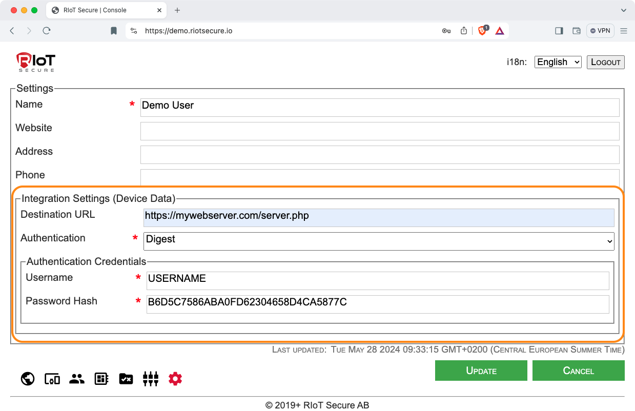
9.1. Integration Settings
These settings are specified on the Settings Screen in the Management Console.
9.1.1. Destination URL
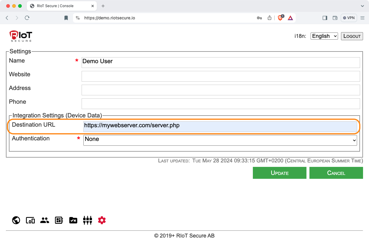
The Destination URL should point to the server that accepts PUT requests with device data. Typically, a web server script is used for this.
The server pointed to by the Destination URL is not part of the RIoT Secure Platform; it is a separate server managed by the customer.
Note that there is a single Destination URL for each tenant. Systems that need to handle multiple applications can route incoming data based on the packet information.
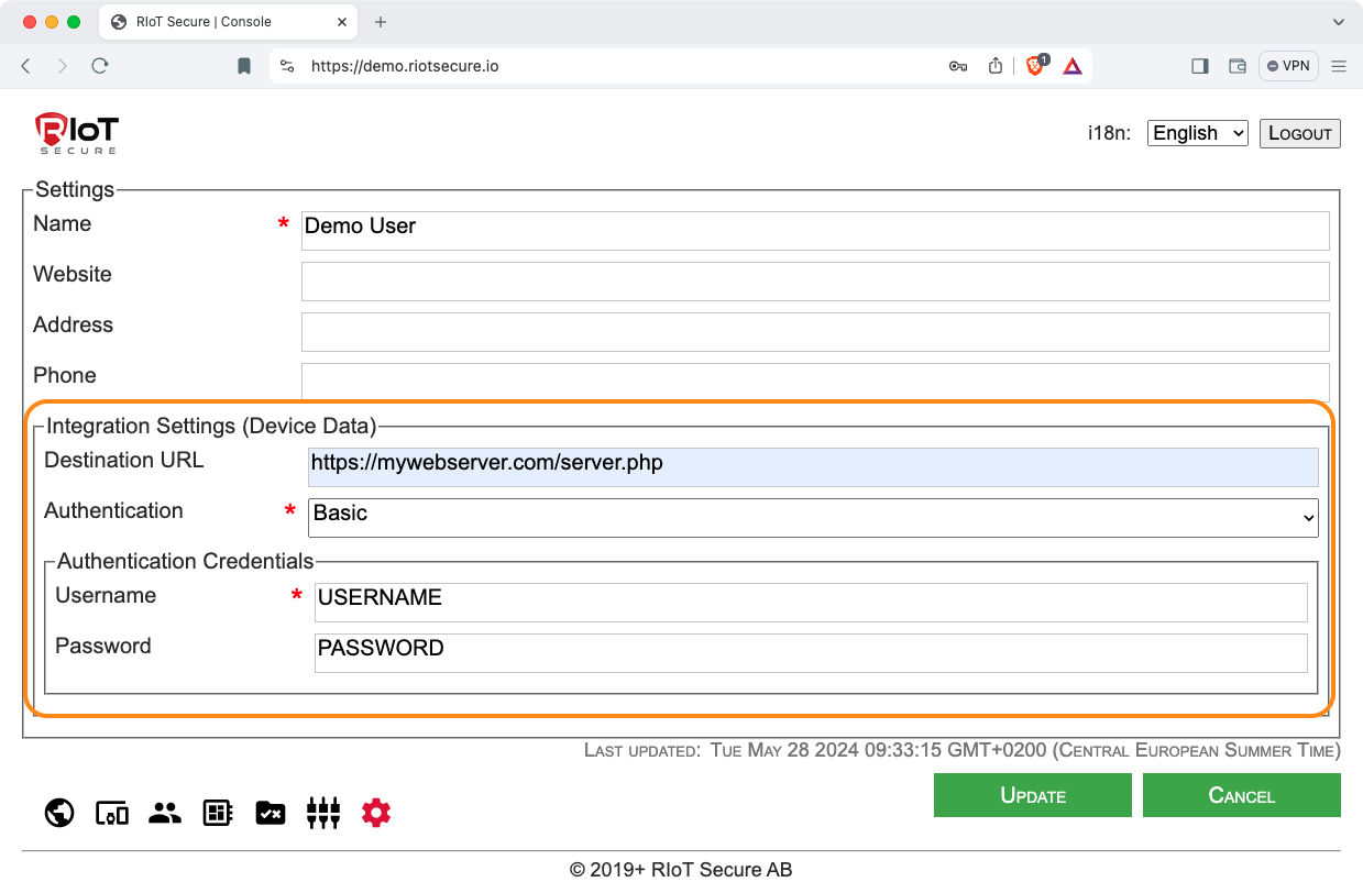
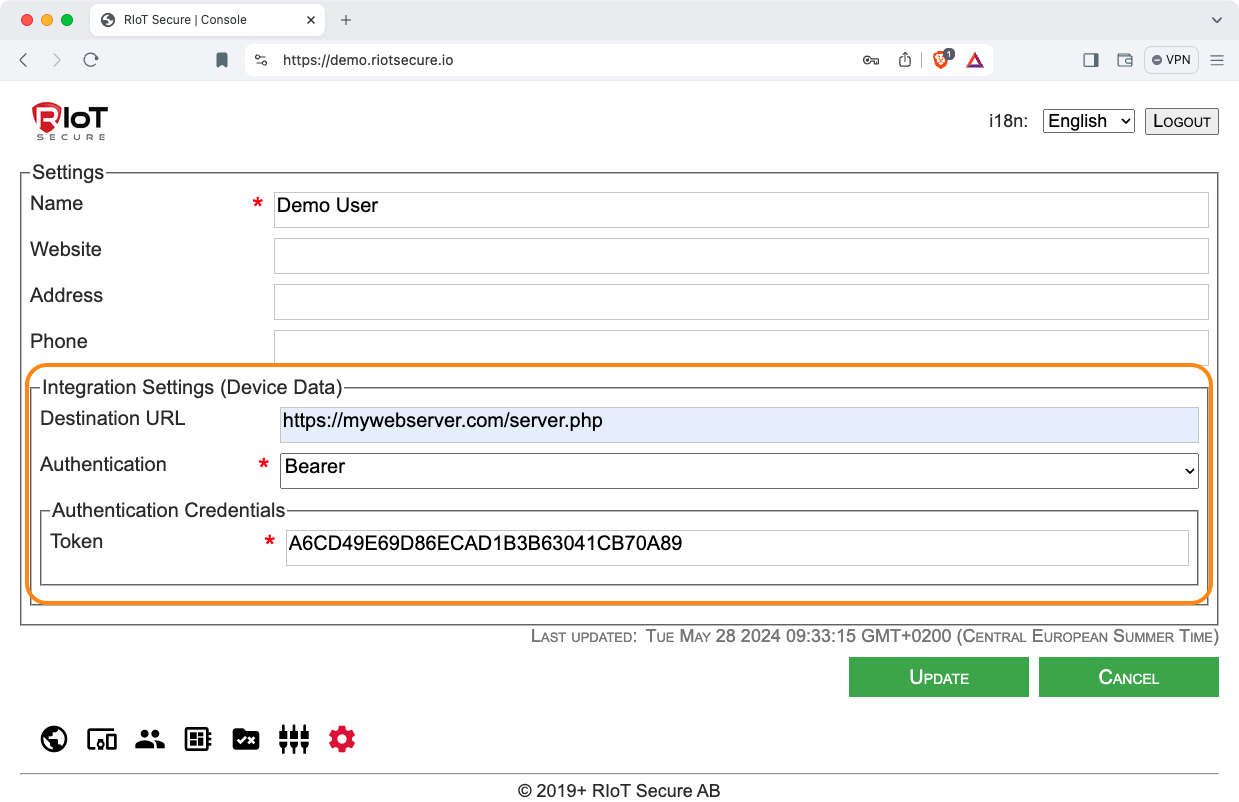
9.1.2. Authentication Settings
There are several authentication methods available for use on the customer cloud server. The following screenshots show how to select the authentication method in the Management Console.
Basic Authentication
Bearer Authentication
Digest Authentication
9.2. Enable Integration Device Setting
This setting is found on the Devices Screen in the Management Console.
On the Devices Screen, click on a device entry to edit the device, and turn on the Integration Enabled setting.
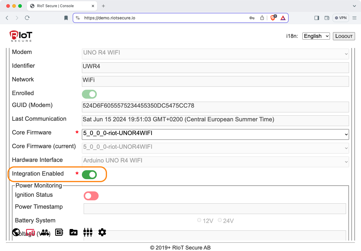
This setting must be enabled for each device that sends data to the customer cloud.
If no data is seen on the cloud server, check that this setting is enabled o all devices that communicate with the cloud.